MTP Level 1
The Signaling Data Link corresponds to the Physical Layer of the OSI model. It defines the physical and the electrical characteristics of the signaling link, connecting two signaling nodes. The Signaling Data Link is a bidirectional physical connection. The physical interfaces initially defined by ITU-T include:
■ E1, 2.048 Mb/s, 64-Kb/s channel
■ T1/DS1, 1.544 Mb/s, 56-Kb/s channel
■ Other interfaces such as RS-232, RS449, DS-0, and V.35
In wireless networks CCST is also used to transport data such as SMS. SMS is a popular service and is growing at fast pace. To meet the increased demand, high speed links (n x 64 or n x 56 Kbps) are need. Furthermore, to exploit less expensive IP transport, new standards such as SIGTRAN are available to support CCS7 over IP.
MTP Level 2
The Signaling Link (MTP Level 2) corresponds to Layer 2 of the OSI model. It is responsible for error-free transmission of messages between two adjacent signaling nodes. The messages related to network management and maintenance and from the user parts are transferred between the nodes in data blocks called signal units (SUs). The functions of MTP Level 2 include:
■ SU delimitation
■ SU alignment
■ Error detection and correction
■ Signaling link error monitoring
■ Initial alignment
■ Flow control
To achieve these functions, MTP Level 2 adds overheads over the Level 3 information. As we will learn later in this section, SU delimitation is achieved by the use of flags at the beginning and the end of an SU, flow control is achieved by using forward and backward sequencing, and error control is achieved by means of cycle redundancy checks.
Signal unit format. There are three different types of signal unit that are transmitted via a signaling link:
Message signal unit (MSU) carries signaling information from the user parts for call control, network management, and maintenance. For example, ISUP MSUs carry call control messages for an ISDN call.
Link status signal unit (LSSU) carries link status control information.
Fill-in signal unit (FISU) is transmitted on the signaling link when there is no MSU or LSSU available to send.
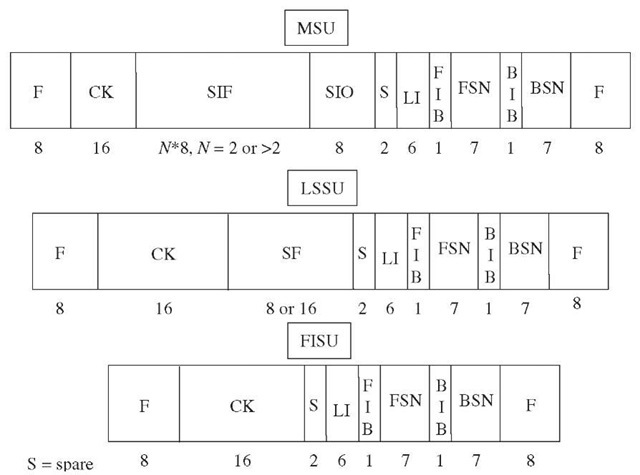
The format of different types of SUs is illustrated in Figure 2-3, where:
F: Flag indicates the beginning and the end of a SU. Flag pattern = 01111110, bit stuffing is used to avoid occurrence of this pattern elsewhere in the SU.
CK: Cycle redundancy check is a 16-bit checksum of an SU.
BSN: Backward sequence number
BIB: Backward indicator bit
FSN: Forward sequence number
FIB: Forward indicator bit
Figure 2-3 CCS7 message structure.
The BSN, BIB, FSN, and FIB fields are used for error and flow control. The flow control is based on a sliding window mechanism and error control is based on go-back-N automatic repeat request (ARQ) mechanism.
LI: Length indicator indicates the number of octets that follow the LI field and precede the CK field. Values of LI for different SUs are as follows:
■ FISU: LI = 0
■ LSSU: LI = 1 or 2
■ MSU: 2 < LI < 63
SIO: Service information octet indicates the nature of a MSU. It consists of two subfields: sub-service field (SSF) and service indicator (SI). The service indicator indicates the user part, e.g., ISUP MSU, SCCP MSU, MTP SNM (Signaling Network Management) MSU etc. The sub-service field allows a distinction between the national and the international CCS7 networks.
SIF: Signaling information field contains Level 3 and Level 4 information, i.e., the routing label and user data. This will be discussed in more detail in the next section.
SF: Status field is part of LSSU. It indicates the status of the signaling link. The valid status indications are:
■ Status indication O: out of alignment
■ Status indication N: normal alignment
■ Status indication E: emergency alignment
■ Status indication OS: out of service
■ Status indication PO: processor outage S: Spare bits,
MTP Level 3
The Signaling Network (MTP Level 3) handles functions and procedures related to signaling message routing and network management. The MTP Level 2 is concerned with the individual signaling link, while MTP Level 3 functions relate to overall network aspects.
As Figure 2-4 illustrates, MTP Level 3 includes functions related to message handling and functions related to network management.
Message handling. The purpose of the message handling part in each signaling node is to transfer a signaling message originated by a particular user part to the same user part at the destination point indicated by the sender. The message handling comprises three functions: routing, discrimination, and distribution. Each signaling node uses the routing function to determine the outgoing signaling link to be used to forward the message.
Figure 2-4 Signaling Network functions.
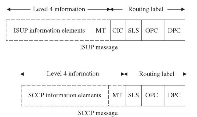
The discrimination function is used to determine if a message received is destined to its node or is to be relayed to another node. The distribution function determines the user part to which a message should be delivered. The message handling decisions are based on the routing label contained in the SIF field. Figure 2-5 illustrates the contents of SIF in ISUP and SCCP MSUs. The routing label contains originating and destination point codes and a signaling link selection code.
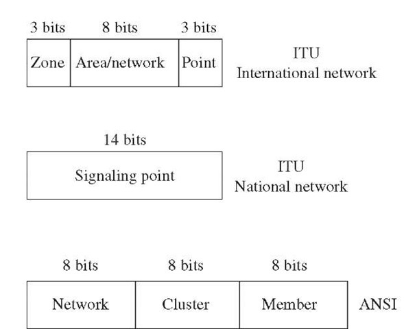
Each signaling node in a CCS7 network is uniquely identified by its point code. The originating point code (OPC) indicates the source of the message, while the destination point code (DPC) identifies the destination of the message. Figure 2-6 shows the format of point codes adopted by ANSI and ITU-T standards.
Figure 2-5 Signaling information field.
ITU-T point codes use 14 bits. Typically, a single number, e.g., 5555, is used to express a point code in a national network. For the international network, it is generally stated in terms of zone, area/network, and signaling point identification number, e.g., 6-0-0.
ANSI point codes use 24 bits (3 octets). It consists of network, cluster, and member octets, e.g., 22-7-0.
The Signaling link selection (SLS) is used to indicate the link in a linkset connecting two adjacent signaling points, over which a signaling message is to be routed. In practice, more than one link is used to connect signaling points. These links share the signaling load.
Signaling network management. The signaling routeset availability objective set by the CCS7 specifications is very stringent. It calls for 99.9998% or better availability. This is equivalent to no more than 10 minutes unavailability per year for any route. This goal is achieved by monitoring the status of each link, with capability to reroute signaling traffic to overcome link degradation or outage. Unlike other systems where the network management part is outside the scope, the CCS7 includes this functionality to achieve desired routeset availability goals. The Signaling network management functions are divided into three categories:
■ Signaling link management
■ Signaling traffic management
■ Signaling route management
Figure 2-6 Signaling point codes format.
Signaling link management. The signaling link management function controls the links locally connected to an SP. This function ensures that predetermined linkset capabilities are maintained. It initiates action to activate additional links if required in the event of signaling link failure. The procedures supported by signaling link management functions are:
■ Link activation
■ Link restoration
■ Link deactivation
■ Linkset activation
Signaling traffic management. The signaling traffic management function is used to divert the signaling traffic from a link or a route to one or more different links or routes. This function, for example, could be used to divert the signaling traffic carried by the unavailable link to other available links. The redistribution of traffic may also be required to ease the congestion on one particular link or route. The signaling traffic management functions include the following procedures:
■ Changeover
■ Changeback
■ Forced rerouting
■ Controlled rerouting
■ Management inhibiting
■ MTP restart
■ Signaling traffic flow control
Signaling route management. The signaling route management functions are used to exchange signaling route availability information between the signaling nodes in a CCS7 network. The signaling traffic management functions include the following procedures:
■ Transfer prohibited
■ Transfer restricted
■ Transfer allowed
■ Signaling routeset test
■ Signaling routeset congestion and transfer control


