By : James W Zubrick
Email: j.zubrick@hvcc.edu
HPLC. Is it high-performance liquid chromatography or high-pressure liquid chromatography or something else? It’s probably easier to consider it a delicate blend of wet-column chromatography and gas chromatography (see Chapters 20 and 24, respectively).
Rather than letting gravity pull the solvent through the powdered adsorbent, the liquid is pumped through under pressure. Initially, high pressures [1000-5000 psig (pounds per square inch gauge), i.e., not absolute] were used to push a liquid through a tightly packed solid. But the technique works well at lower pressures 250 psig), hence the name high-performance liquid chromatography.
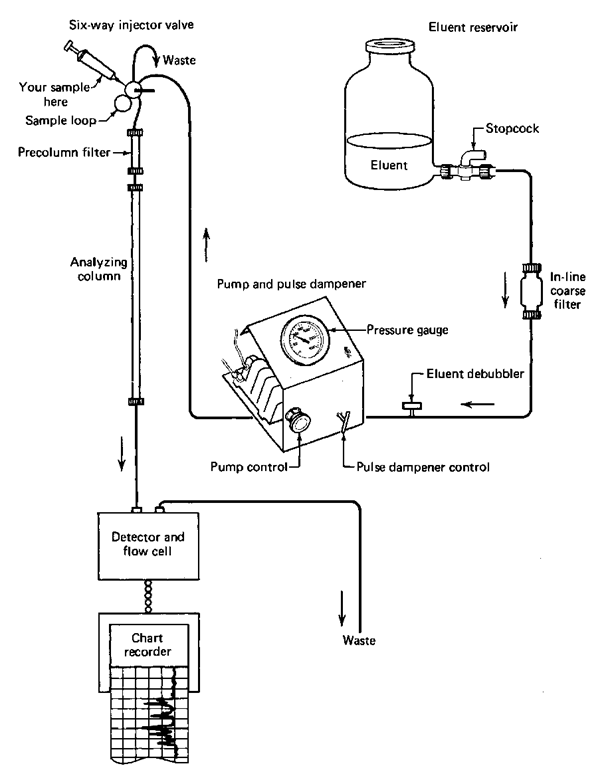
From there on, the setup (Fig. 110) resembles gas chromatography very closely. Although a moving liquid phase replaces the helium stream, compounds are put onto a column through an injection port, they separate inside a chromatographic column in the same way as in GC by spending more or less time in a moving liquid now, and the separated compounds pass through a detector. There the amounts of each compound as they go by the detector are turned into electrical signals and displayed on a chart recorder as HPLC peaks that look just like GC peaks. You should also get the feeling that the analysis of these HPLC traces is done in the same manner as GC traces, because it is.
Again, there’s a lot of variety among HPLC systems, so what I say won’t necessarily apply to your system in every respect. But it should help. I’ve based my observations on a Glencoe HPLC unit. It is simple and rugged, performs very well, and uses very common components carried by almost every HPLC supplier. Parts are easy to get.
That’s probably why the company has stopped making this unit. Anything simple and rugged is not likely to need a lot of attention, nor is it likely to go out of fashion, and there’s little profit in that. The individual pieces can be bought from many chromatographic supply houses. Just follow the directions for connections given here.
THE MOBILE PHASE: LIQUID
If you use only one liquid, either neat or as a mixture, the entire chromato-gram is said to be isochratic. There are units that can deliver varying solvent compositions over time. These are called gradient elution systems.
Fig. 110 Block diagram of an HPLC setup.
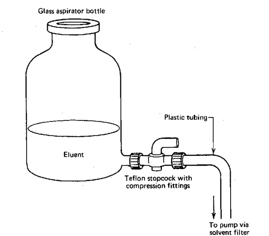
For an isochratic system, you usually use a single solution, or a neat liquid, and put it into the solvent reservoir, generally a glass bottle with a stopcock at the bottom to let the solvent out (Fig. 111). The solvent travels out of the bottom of the reservoir and usually through a solvent filter that traps out any fairly large, insoluble impurities that may be in the solvent.
It is important, if you’re making up the eluent yourself, to follow the directions scrupulously. Think about it. If you wet the entire system with the wrong eluent, you can wait a very long time for the correct eluent to reestablish the correct conditions.
A Bubble Trap
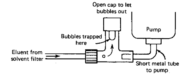
Air bubbles are the nasties in HPLC work. They cause the same type of troubles as with wet-column chromatography, and you just don’t want them. So there’s usually a bubble trap (Fig. 112) before the eluent reaches the pump. This device is quite simple, really. Bubbles in the eluent stream rise up the center pipe and are trapped there. To get rid of the bubbles, you open the cap at the top. Solvent then rises in the tube and pushes the bubbles out. You have to be extremely careful about bubbles if you’re the one to start the setup or if the solvent tank has run out. Normally, one bubble purge per day is enough.
Fig. 111 Aspirator bottle used to deliver eluent.
Fig. 112 Common bubble trap.
The Pump
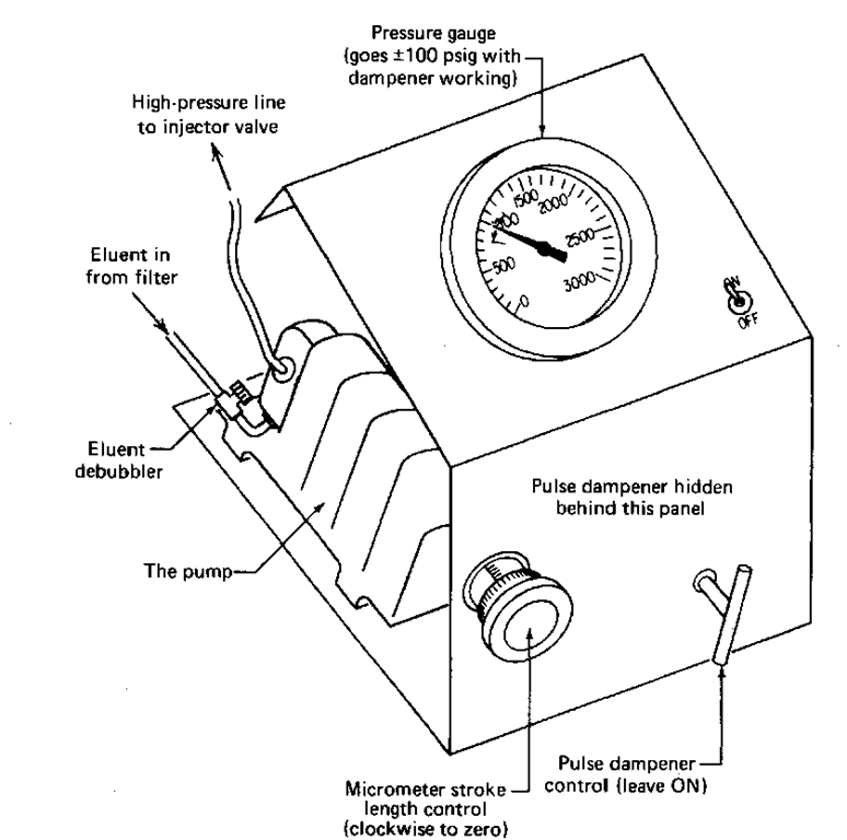
The most common pumping system is the reciprocating pump. Milton Roy makes a pretty good model. The pump has a reciprocating ruby rod that moves back and forth. On the backstroke, the pump loads up on a little bit of solvent, then it squirts it out, under pressure, on the forward stroke. If you want to increase the amount of liquid going through the system, you can dial the length of the stroke, from zero to a preset maximum, using the micrometer at the front of the pump (see Fig. 113). Use a fully clockwise setting, and the stroke length is zero — no solvent flow. A fully counterclockwise setting gives the maximum stroke length—maximum solvent flow. If you have a chance to work with this type of pump, always turn the micrometer fully clockwise to give a zero stroke length before you start the pump. If there is a stroke length set before you turn the pump on, the first smack can damage the reciprocating ruby rod. And it is not cheap.
The Pulse Dampener
Because the rod reciprocates (i.e., goes back and forth) you’d expect huge swings in pressure, pulses of pressure, to occur. That’s why they make pulse dampeners. A coiled tube is hooked to the pump on the side opposite the column (Fig. 113). It is filled with the eluent that’s going through the system. On the forward stroke, solvent is compressed into this tube and at the same time, a shot of solvent is pushed onto the column. On the backstroke, while the pump chamber fills up again, the eluent we just pressed into the pulse dampener squirts out into the column. Valves in the pump take care of directing the flow. With the eluent in the pulse dampener tubing taking up the slack, the huge variations in pressure, from essentially zero to perhaps 1000 psig, are evened out. They don’t disappear, going about 100 psig either way, but these dampened pulses are now too small to be picked up on the detector. They don’t show up on the chart recorder either.
Fig. 113 Pump, pulse dampener, and pressure-gauge unit.
HPLC SAMPLE PREPARATION
Samples for HPLC must be liquids or solutions. It would be nice if the solvent you’ve dissolved your solid sample in were the same as the eluent.
It is absolutely crucial that you preclean your sample. Any decomposed or insoluble material will stick to the top of the column and can continually poison further runs. There are a few ways to keep your column clean.
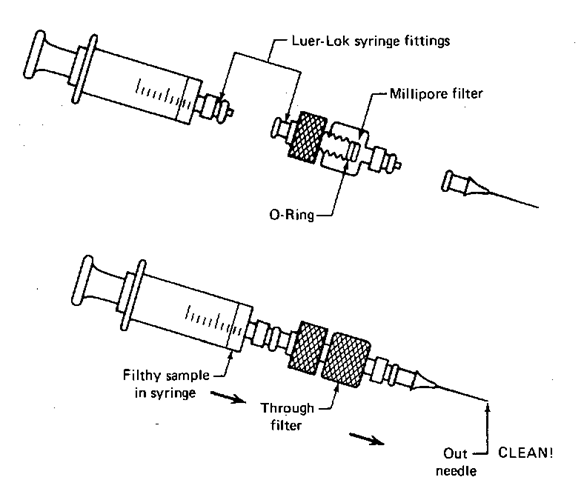
1. The Swinney adapter (Fig. 114). This handy unit locks onto a syringe already filled with your sample. Then you push the sample slowly through a Millipore filter to trap insoluble particles. This does not, however, get rid of soluble tars that can ruin the column. (Oh. Don’t confuse the filters with the papers that separate them. It’s embarrassing.)
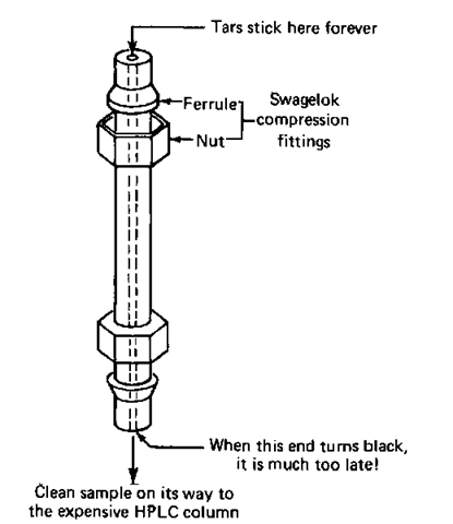
2. The precolumn filter (Fig. 115). Add a tiny column, filled with exactly the same material as the main column, and let this small column get contaminated. Then unscrew it, clean out the gunk and adsorbant, and refill it with fresh column packing. The disadvantage is that you don’t really know when the garbage is going to poison the entire precolumn filter and then start ruining the analyzing column. The only way to find out whether you have to clean the precolumn is to take it out of the instrument. You really want to clean it out long before the contaminants start to show up at the precolumn exit.
Fig. 114 The Swinney adapter and syringe parts.
Fig. 115 The precolumn filter.
HPLC SAMPLE INTRODUCTION
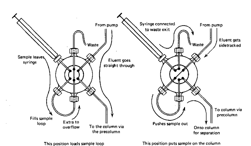
This is the equivalent of the injection port for the GC technique. With GC you could inject through a rubber septum directly onto the column. With HPLC it’s very difficult to inject against a liquid stream moving at possibly 1000 psig. That’s why they invented injection port valves for HPLC: you put your sample into an injection loop on the valve that is not in the liquid stream, then turn the valve, and voila, your sample is in the stream, headed for the column. The valve (Fig. 116) has two positions.
1. Normal solvent flow. In this position, the eluent comes into the valve, goes around, and comes on out into the column without any bother. You load the sample loop in this position.
2. Sample introduction. Flipped this way, the eluent is pumped through the sample loop and any sample there is carried along and into the column. You put the sample on the column in this position.
SAMPLE IN THE COLUMN
Once the sample is in the column, there’s not much difference between what happens here and what happens in paper, thin-layer, vapor-phase (gas), wet-column, or dry-column chromatography. The components in the mixture will stay on the stationary phase, or move in the mobile phase for different times and end up at different places when you stop the experiment.
So what’s the advantage? You can separate and detect microgram quantities of solid samples much as in GC. And you can’t do solids all that well by GC because you have to vaporize your solid sample, probably decomposing it.
Flg. 116 The sample injector valve.
A novel development for HPLC is something called bonded reversed-phase columns, where the stationary phase is a nonpolar hydrocarbon, chemically bonded to a solid support. You can use these with aqueous eluents, usually alcohol-water mixtures. So you have a polar eluent and a nonpolar stationary phase, something that does not usually occur for ordinary wet-col -umn chromatography. One advantage is that you don’t need to use anhydrous eluents (very small amounts of water can change the character of normal phase columns) with reversed-phase columns.
SAMPLE AT THE DETECTOR
There are many HPLC detectors that can turn the presence of your compound into an electrical signal to be written on a chart recorder. Time was the refractive index detector was common. Clean eluent, used as a reference, went through one side of the detector, and the eluent with the samples went through the other side. A difference in the refractive index between the sample and reference caused an electrical signal to be generated arid sent to a chart recorder. If you’ve read the section on gas chromatography and looked ahead at infrared, you shouldn’t be surprised to find both a sample and a reference. I did tell you the reference/sample pair is common in instrumentation.
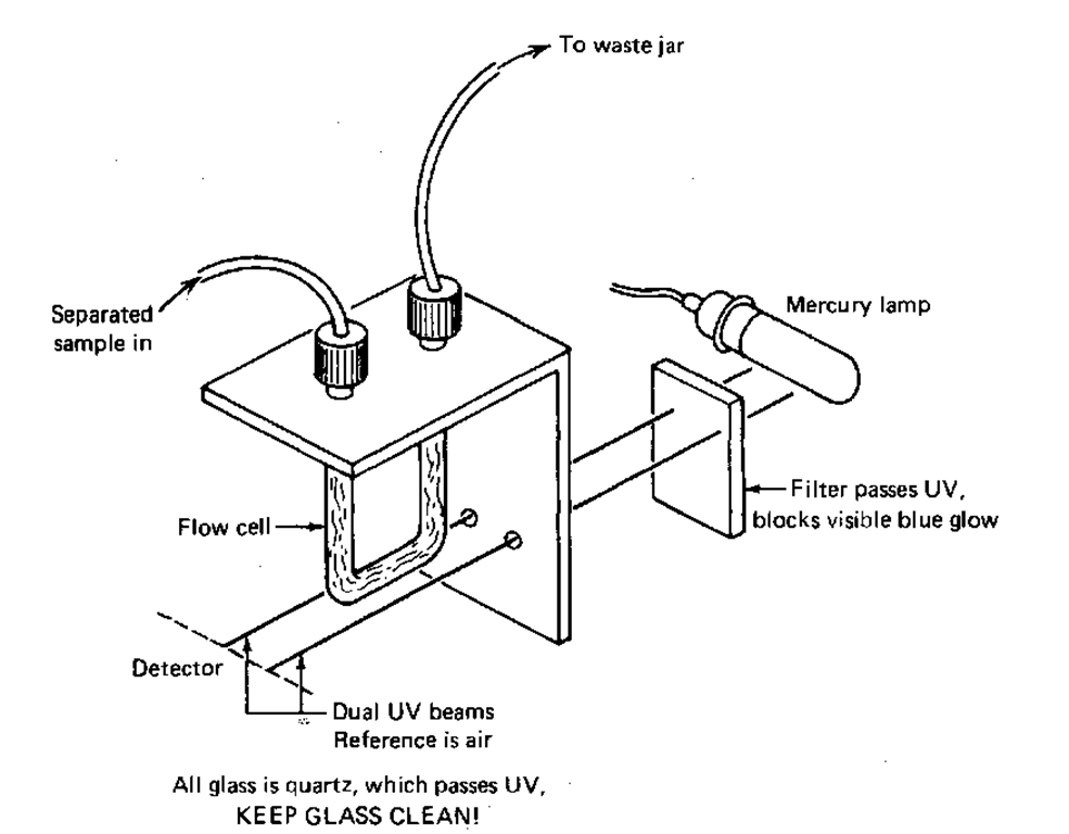
More recently, UV detectors (Fig. 117) have become more popular. UV radiation is beyond the purple end of the rainbow, the energy from which great tans are made. So, if you set up a small mercury vapor lamp with a power supply to light it up, you’ll have a source of UV light. It’s usually filtered to let through only the wavelengths of 180 and/or 254 nm. (And where have you met that number before? TLC plates, maybe?) This UV light then passes through a flow cell that has the eluent and your separated sample flowing through it against air as a reference. When your samples come through the cell, they absorb the UV, and an electrical signal is generated. Yes, the signal goes to a chart recorder and shows up as HPLC peaks.
Fig. 117 Cutaway view of a HPLC UV detector.
SAMPLE ON THE CHART RECORDER
Go back and read about HPLC peak interpretation in the section on GC peak interpretation (“Sample on the Chart Recorder”). The analysis is exactly the same, retention times, peak areas, baselines,… all that.
PARAMETERS, PARAMETERS
To get the best LC trace from a given column, there are lots of things you can do, most of them the same as for GC (see “Gas Chromatography, Parameters, Parameters”).
Eluent Flow Rate
The faster the eluent flows ,the faster the compounds are pushed through the column. Because they spend less time in the stationary phase, they don’t separate as well and the LCpeaks come out very sharp but not well separated. If you slow the eluent down too much, the compounds spend so much time in the stationary phase that the peaks broaden and overlap gets very bad. The optimum is, as always, the best separation you need, in the shortest amount of time. One big difference in LC is the need to worry about back-pressure. If you try for very high flow rates, the LC column packing tends to collapse under the pressure of the liquid. This, then, is the cause of the back-pressure, resistance of the column packing. If the pressures get too high, you may burst the tubing in the system, damaging the pump…..all sorts of fun things.
Temperature
Not many LC setups have ovens for temperatures like those for GC. This is because eluents tend to boil at temperatures much lower than the compounds on the column, which are usually solids anyway. And eluent bubbling problems are bad enough, without actually boiling the solvent in the column. This is not to say that LC results are independent of temperature. They’re not. But if a column oven for LC is present, its purpose more likely is to keep stray drafts and sudden chills away than to have a hot time.
Eluent Composition
You can vary the composition of the eluent (mobile phase) in HPLC a lot more than in GC, so there’s not really much correspondence. Substitute nitrogen for helium in GC and usually the sensitivity decreases, but the retention times stay the same. Changing the mobile phases—the gases—in GC doesn’t have a very big effect on the separation or retention time.
There are much better parallels to HPLC: TLC or column chromatography. Vary the eluents in these techniques and you get widely different results. With a normal-phase silica-based column, you can get results similar to those from silica gel TLC plates.
