Introduction
In many fields such as health or robotics industry, reproducing the human visual system (HVS) behavior is a widely sought aim. Actually a system able to reproduce even partially the HVS could be very helpful, on the one hand, for people with vision diseases, and, on the other hand, for autonomous robots.
Historically, the earliest reports of artificially induced phosphenes were associated with direct cortical stimulation Tong (2003). Since then devices have been developed that target ùany different sites along the visual pathway Troyk (2003).These devices can be categorized according to the site of action along the visual pathway into cortical, sub-cortical, optic nerve ane retinal prostheses. Although the earliest reports involved cortical stimulation, with the advancements in surgical techniques and bioengineering, the retinal prosthesis or artificial retina has become the most advanced visual prosthesis Wyatt (2011).
In this topic, both applications will be presented after the theoretical context, the state of the art and motivations. Furthermore, a full system will be described including a servo-motorized camera (acquisition), specific image processing software and artificial intelligence software for exploration of complex scenes. This topic also deals with image analysis and interpretation.
Human visual system
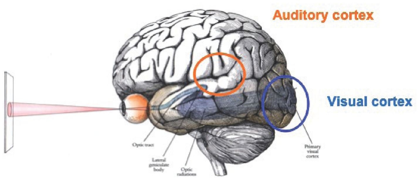
The human visual system is made of different parts: eyes, nerves and brain. In a coarse way, eyes achieve image acquisition, nerves data transmission and brain data processing (Fig. 1).
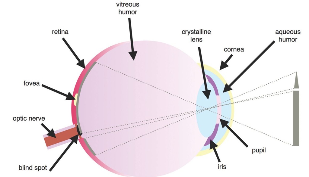
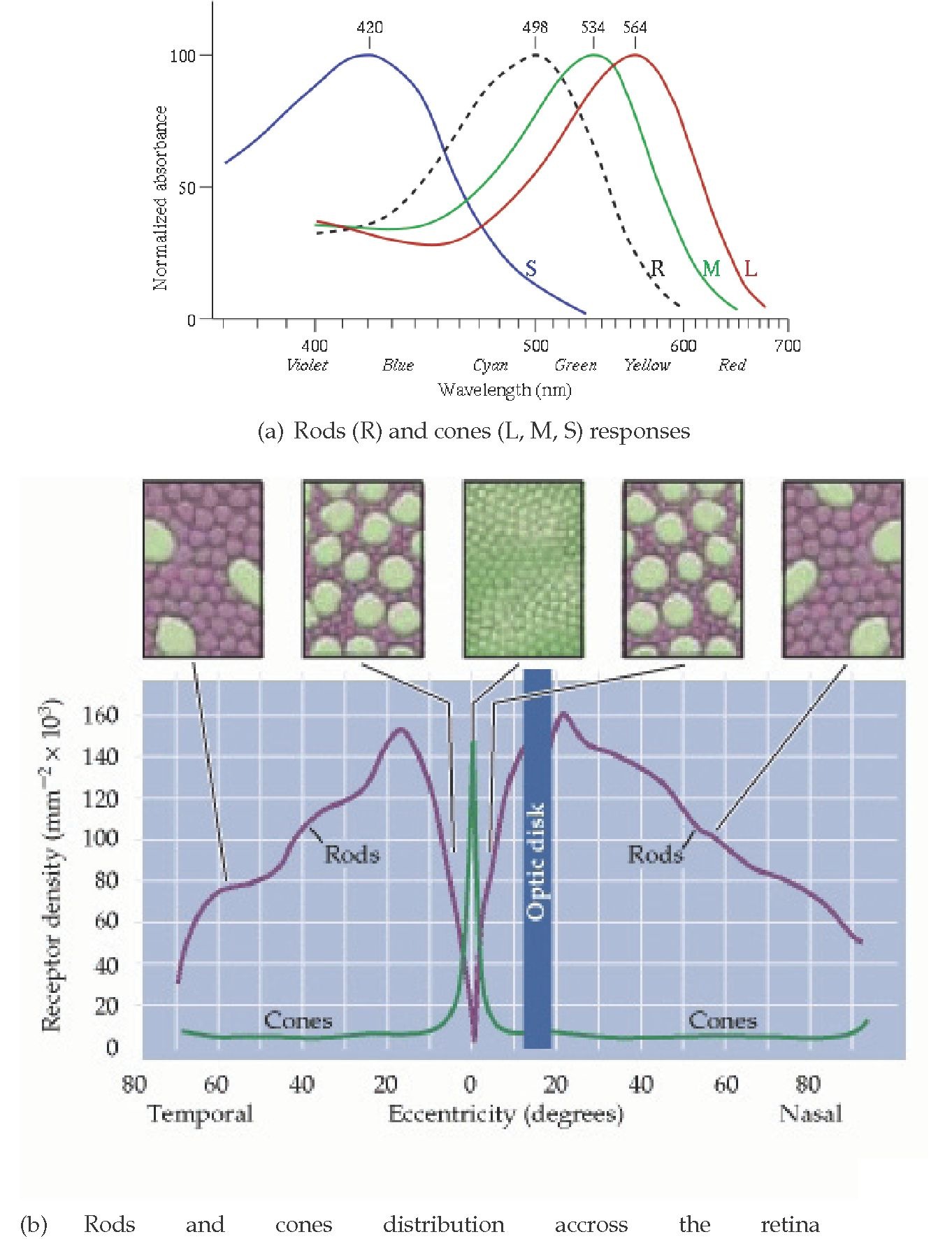
The eye (Fig. 2) acquires images through the pupil and visual information is processed by retina photoreceptors. There exist two kinds of photoreceptors: rods and cones. Rods are dedicated to light intensity acquisition. They are efficient in scotopic and mesopic conditions. Cones are specifically sensitive to colors and require a minimal light level (photopic and mesopic conditions). There are three different types of cones sensitive for different wavelengths.
Fig. 3a shows the photoreceptors responses and Fig. 3b their distribution accross the retina from the foveal area (at the center of gaze) to the peripheral area. At the top of Fig. 3b, small parts of retina are presented with cones in green and rods in pink. This outlines that the repartition of cones and rods varies on the retina surface according to the distance to the center of gaze.
Fig. 1. Human visual system
Fig. 2. Human eye
Most of the cones are located in the fovea (retina center) and rods are essentially present in periphery. Then light energy data are turned into electrochemical energy data to be carried to the visual cortex through the optic nerves. The two optic nerves converge at a point called optic chiasm (Fig. 4), where fibers of the nasal side cross to the other brain side, whereas fibers of the temporal side do not. Then the optic nerves become the optic tracts. The optic tracts reach the lateral geniculate nucleus (LGN). Here begins the processing of visual data with back and forth between the LGN and the visual cortex.
Why a bionic eye?
Blindness affects over 40 millions people around the world. In the medical field, providing a prosthesis to blind or quasi-blind people is an ambitious task that requires a huge sum of knowledge in different fields such as microelectronics, computer vision and image processing and analysis, but also in the medical field: ophtalmology and neurosciences.
Fig. 3. Rods and cones features
Cognitive studies determining the human behavior when facing a new scene are lead in parallel in order to validate methods by comparing them to a human observer’s abilities. Several solutions are offered to plug an electronic device to the visual system (Fig. 4). First of all, retina implants can be plugged either to the retina or to the optic nerve.
Fig. 4. Human visual system and solutions for electronic device plugins
Such a solution requires image processing in order to integrate data and make them understandable by the brain. No image analysis is necessary as data will be processed by the visual cortex itself. But the patient must be free of pathology at least at the optic nerve, so that data transmission to the brain can be achieved. In another way, retina implants can directly stimulate the retina photoreceptors. That means that the retina too must be in working order. Secondly, when either the retina or the optic nerve is damaged, only cerebral implants can be considered, as they directly stimulate neurons. In this context, image analysis is required in order to mimick at least the LGN behavior.
Why now?
The development of biological implantable devices incorporating microelectronic circuitry requires advanced fabrication techniques which are now possible. The importance of device stability stems from the fact that the microelectronics have to function properly within the relatively harsh environment of the human body. This represents a major challenge in developing implantable devices with long-term system performance while reducing their overall size.
Biomedical systems are one example of ultra low power electronics is paramount for multiple reasons [Sarpeshkar (2010)]. For example, these systems are implanted within the body and need to be small, light-weighted with minimal dissipation in the tissue that surrounds them. In order to obtain implantable device, some constraints have to be taken into account such as:
• The size of the device
• The type of the technology (flexible or not) in order to be accepted by the human body
• The circuit consumption in order to optimize the battery life
• The performance circuit
The low power hand reminds us that the power consumption of a system is always defined by five considerations as shown on Fig.5:
Fig. 5. Low power Hand for low power applications


