Abstract
We introduce a novel micromechanical structure that exhibits two regions of stable linear positive and negative stiffness. Springs, cantilevers, beams and any other geometry that display an increasing return force that is proportional to the displacement can be considered to have a "Hookean" positive spring constant, or stiffness. Less well known is the opposite characteristic of a reducing return force for a given deflection, or negative stiffness. Unfortunately many simple negative stiffness structures demonstrate either unstable buckling which can require extraneous moving constraints during deflection, so as not to deform out of useful shape, or are highly nonlinear such as the disk cone spring. In MEMS, buckling caused by stress at the interface of silicon and thermally grown SiO2 causes tensile and compressive forces that will warp structures if the silicon layer is thin enough. The structure presented here utilizes this effect but overcomes its limitations and empirically demonstrates linearity in both regions. The structure is manufactured using only common micromachining techniques and can be made in situ with other devices.
Introduction
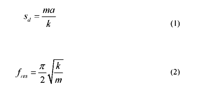
The correct electrical operation of many MEMS devices can depend on spatial changes between surfaces or even bending of materials which change electrical properties. Small changes in distances can easily be detected through capacitive sensing circuits and flexing of piezoresistive materials can be measured through changes in electrical potential. MEMS inertial sensors are normally blocks of material suspended by tethers from surrounding bulk material [1]. The tether’s thickness, length, shape and material are determined by the desired stiffness for a needed displacement sensitivity (formula 1) and resonant frequency (formula 2).
where a is the acceleration, m is mass and k is stiffness. Since a change in mass has opposite effects on sensitivity and resonance, it will be considered as a constant. As a simple example, the displacement (y) formula for a single fixed end cantilever beam, where the force is applied to the free end, is
Disclaimer: The views expressed in this paper are those of the authors and do not reflect the official policy or position of the United States Air Force, Department of Defense, or the U.S. Government.
F is the applied force, L is the length of the beam, E is the Young’s Modulus of the beam material and I is the moment of inertia. Considering only rectangular structures,
B is the width of the cantilever and H is the thickness that is in the axis of the bending moment. Solving for the stiffness k, we arrive at
Negative Stiffness
Looking through the parameters, it is apparent that for a given material (fixed Young’s Modulus), the standard way to mechanically modify the stiffness is by changing the geometry of the cantilever. This modification could be impractical due to size constraints or have undesirable effects on off axis mechanics and the displacement sensitivity. Another method to decrease the overall effective stiffness is by offsetting it with negative stiffness.
Negative structural stiffness is fundamentally a reduction in return force for a given displacement. The mechanical realization of this concept has been used and studied for over 80 years [2]. Many objects which demonstrate this are pre-strained, in a post-buckled state, require potential energy through pre-loading [4] and can only produce it non-linearly. Dynamic modeling of these devices are generally constrained to small relative displacements so that linearization can be assumed allowing for easier design. Figure 1 is a simple spring system which demonstrates a typical theoretical load deflection plot (Figure 2) of a negative stiffness system.
Fig. 1 Simple spring system that demonstrates negative stiffness [4]
Fig. 2 Typical load deflection plot of negative stiffness system [4]
Stiffness, also known as a spring constant, is the slope at any point in the plot. Initially all springs are in a non-loaded state with the upper and lower ends attached to fixed pivots. The center portion is only free to move horizontally. As point a, in Figure 1, is deflected to the left, the springs are compressed, potential energy is added to the system and force increases to the right. This is demonstrated as the linear positive stiffness of k3=10 shown in Figure 2. When the spring forces are in equilibrium around the midpoint, no force is produced right or left, and the system is at the unstable zero point. Any deflection past this point will result in the springs developing force to the right and popping through. The negative stiffness is demonstrated after the inflection point up to the zero point.
Other research has concentrated on using active systems to produce a negative stiffness, such as with electrostatic forces. These systems of course require external power, and development of effective controls systems is ongoing [5]. This paper presents some the preliminary results from the modification of a passive system, the buckled oxide membrane.
Results
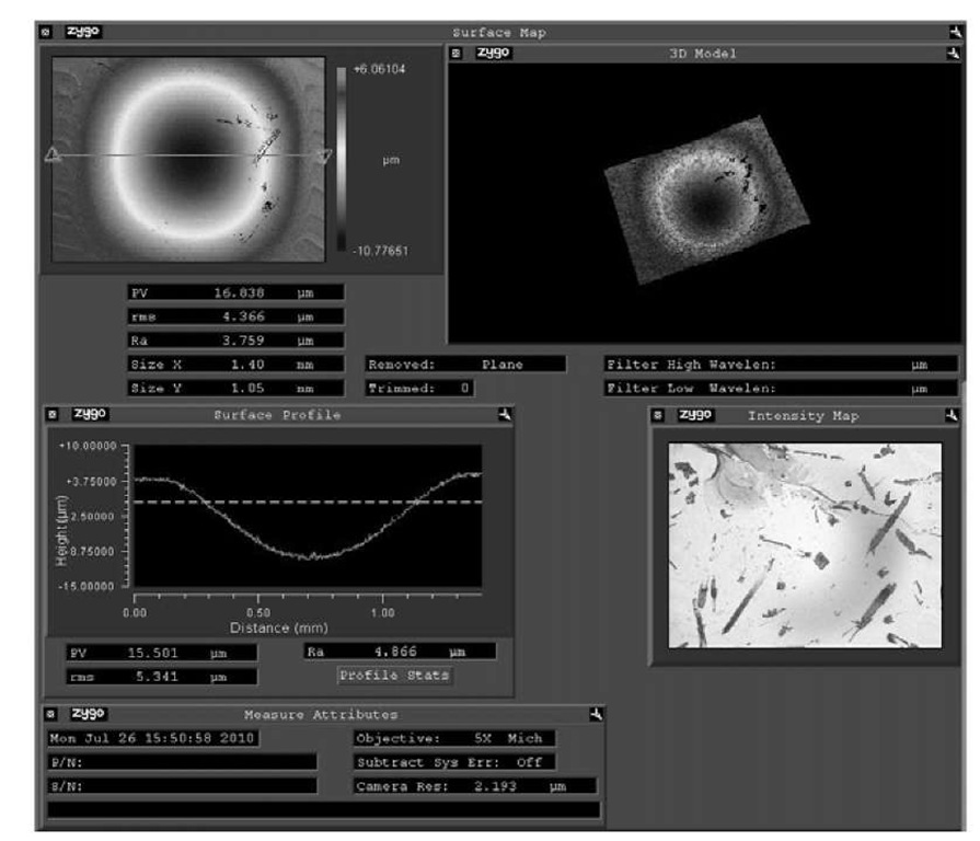
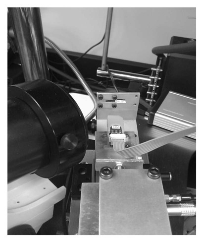
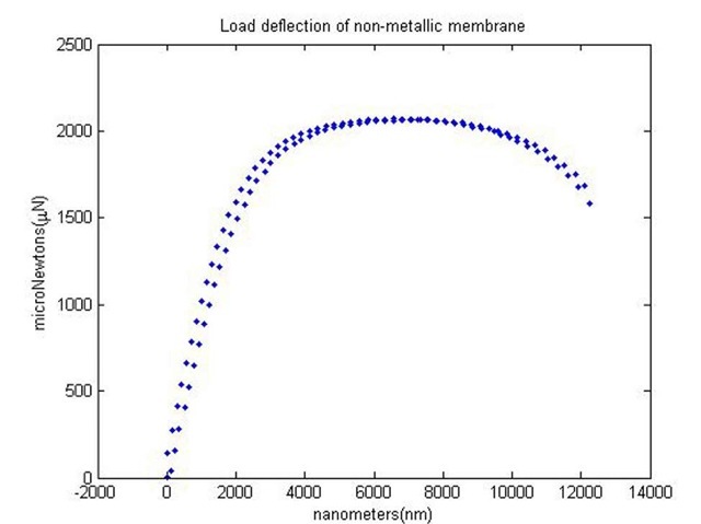
A buckled oxide membrane is an axially symmetric dome that resembles the geometry of Figure 1 if rotated around the k2 spring. A Silicon-On-Insulator (SOI) wafer from Ultrasil Corporation was masked with oxide and bulk micromachined through 1mm x 1mm windows into the substrate (handle) using the DRIE process. The wafer device and handle layers were n type <100> monocrystalline silicon of 5 and 400um thicknesses respectively. The 2um buried oxide layer was used as the stop etch for the DRIE process. The oxide had been thermally grown on the device layer before chemical mechanical polishing and bound to the handle layer per Ultrasil. The oxide layer, due to a different coefficient of expansion than the silicon, is under compressive stress and causes a buckled membrane dome of it and the device layer once released from the handle layer via the DRIE process. The produced membrane is on average 15um higher or lower than the surrounding device layer. The membrane is bistable in that it could either be pushed into or out of the substrate and retain its position (Figure 3). A calibrated capacitive force sensor with .4uN resolution was mounted to a piezo-electric actuator with a 20um range (Figure 4). The force sensor was displaced 200nm at 500ms intervals through the substrate into and away from the crown of a pushed in membrane. The load deflection curve shape was typical of other structures with similar geometry (Figure 5), except for the extended zero stiffness region around the inflection point. The plot gives a general idea of the largest returnable deflection that was achievable without pop through.
Fig. 3 Image of buckled oxide membrane using Zygo White Light Interferometer
Fig. 4 Calibrated capacitive force sensor mounted to piezo electric actuator
Fig. 5 Load deflection plot of pushed in buckled oxide membrane
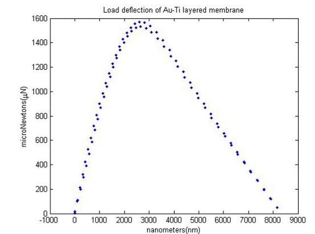
A second set of membranes were manufactured but with thin film metallic layers. Prior to DRIE, a 300A titanium adhesion layer and 3000A gold layer were evaporated onto the device layer. This step reduced the height of the domes to approximately 11um but retained bistability. The deflection test was repeated again, with the results shown in Figure 6.
Fig. 6 Load deflection plot of Au-Ti buckled oxide membrane
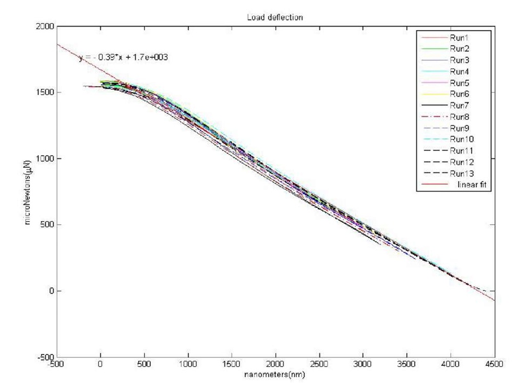
The inflection point is now sharper and the negative stiffness portion has been highly linearized. Curve fitting produces a stiffness of -.39un/nm (-390N/m) over a 4um deflection range in the negative portion (Figure 7).
Fig. 7 Linear curve fit of negative stiffness portion Au-Ti buckled oxide membrane
A literature search has turned up one MEMS structure that exhibits similar load deflection characteristics. A centrally clamped bistable silicon mechanism (Figure 8) produced the plot in Figure 9 [6]. Although the structures have many differences, similarities in their operation may provide insights into operation of the membrane.
Fig. 8 The centrally-clamped parallel-beam bistable mechanism, and its deflection and snap through behavior [6]
Fig. 9 Load deflection plot of the centrally clamped bistable MEMS mechanism [6]
Conclusions
Negative stiffness is potentially useful for selectively tuning the spring constant of micro-mechanical beams found in MEMS sensors and actuators. This paper analyzed buckled oxide membranes, fabricated from SOI wafers, as a test structure for realizing stable negative stiffness. Future work will include investigating other MEMS test structures for optimized negative spring constant tuning.


![Simple spring system that demonstrates negative stiffness [4] Simple spring system that demonstrates negative stiffness [4]](http://what-when-how.com/wp-content/uploads/2011/07/tmp16264_thumb_thumb.jpg)
![Typical load deflection plot of negative stiffness system [4] Typical load deflection plot of negative stiffness system [4]](http://what-when-how.com/wp-content/uploads/2011/07/tmp16265_thumb_thumb.jpg)
![The centrally-clamped parallel-beam bistable mechanism, and its deflection and snap through behavior [6] The centrally-clamped parallel-beam bistable mechanism, and its deflection and snap through behavior [6]](http://what-when-how.com/wp-content/uploads/2011/07/tmp16271_thumb_thumb.jpg)
![Load deflection plot of the centrally clamped bistable MEMS mechanism [6] Load deflection plot of the centrally clamped bistable MEMS mechanism [6]](http://what-when-how.com/wp-content/uploads/2011/07/tmp16272_thumb_thumb.jpg)
