OVERVIEW
The UML (Unified Modeling language) has become a standard in design of object-oriented computer systems (Schach 2004). UML provides for the use of stereotypes to extend the utility of its base capabilities. In the design and construction of business systems, the use of stereotypes is particularly useful stereotypes, and this article defines and illustrates these.
UML STEREOTYPES
“Stereotypes are the core extension mechanism of UML. If you find that you need a modeling construct that isn’t in the UML but it is similar to something that is, you treat your construct as a stereotype” (Fowler & Kendall, 2000). The stereotype is a semantic added to an existing model element and diagrammatically it consists of the stereotype name inside of guillemots (a.k.a., chevrons) within the selected model element. The guillemot looks like a double angle bracket (<< … >>), but it is a single character in extended font libraries (Brown, 2002). The UML defines about 40 of these stereotypes such as “<<becomes>>”, “<<include>>”, and “<<signal>” (Scott, 2001). However, these 40 standard stereotypes are not particularly useful in business models and do not add the meaning necessary for automatic code generation in a UML CASE tool.
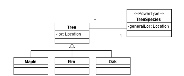
One common general use of the stereotype is for a metaclass. A metaclass is a class whose instances are classes, and these are typically used in systems in which one needs to declare classes at run time (Eriksson & Penker, 1998). A similar general use is for powertypes. A powertype is an object type (class) whose instances are subtypes of another object type. Figure 1 shows an example of the use of stereotypes for powertypes (Martin & Odell, 1998).
USER DEFINED STEREOTYPES FOR BUSINESS SYSTEMS
In the design of business systems we have found some stereotypes that were useful, and two stereotypes that are extremely useful. When defining stereotypes it is necessary to describe (Eriksson & Penker, 1998):
1. on which (UML) element the user-defined stereotype should be based;
2. the new semantics the stereotype adds or refines; and
3. pne or more examples of how to implement the user-defined stereotype.
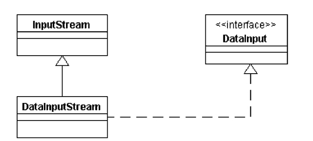
A common use of stereotypes in business systems is for interfaces as found in Java or CORBA; this is shown in Figure 2. An interface typically has public functionality but not data (unless holding data for global constants). The class model element has been modified with the “<<interface>>” notation. This is commonly used for UML CASE products that do not have separate interface symbols or where these symbols do not allow data (i.e., global constants).
Figure 1.
Still another common stereotype usage in business systems is to clarify or extend a relationship. Figure 3 shows a stereotype called “history” which implies a “many” cardinality for history purposes, that is, each person has zero or one current employers but may have many employers in terms of the employee’s history. It may imply some common functionality upon code generation such as (Fowler & Kendall, 2000):Company Employee::get Company(Date);
CODE WRITING AND GENERATION
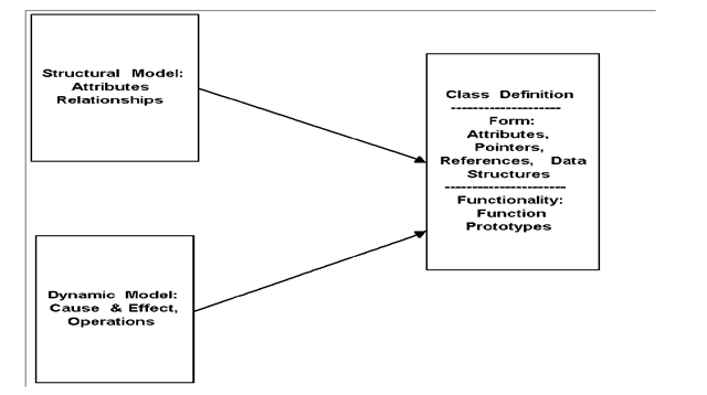
Most modern UML CASE (Computer Aided Software Engineering) products can generate “skeleton” classes from the UML class diagrams and possibly other diagrams. For business systems design, we need to write the code for our classes (usually implemented in Java or C++) based on both the Structural Model (UML Class Diagram) and the Dynamic Model (UML Activity Diagram). This process is shown in Figure 4. It is very important that consistency between the two diagrams is achieved.
Many such CASE products allow the user to write their own “class generation scripts” in some proprietary scripting language or in a general scripting language (i.e., Python). With user defined stereotypes, the user can modify the class generation script code to use their stereotypes as needed.
Figure 2.
Figure 3.
Figure 4.
Figure 5.
Figure 6.
RELATIONSHIP OBJECT TYPES
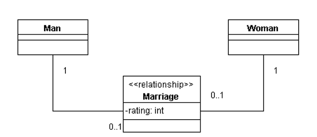
As an example, consider a simple association between two object types. Often these simple relationships need to be modeled as object types because these relationships have data content and/or functionality. Figure 5 shows a simple association between two object types representing the relationship “current marriage”. If we need to maintain an attribute on each marriage (such as rating), then we can more effectively represent the relationship as an object type as shown in Figure 6. Here we use the “relationship” stereotype to indicate that this object type is a relationship; and the code generation can use a more appropriate class representation. Others authors have suggested other notations for relationship object types such as “placeholders” (Martin & Odell, 1998), and UML suggests using the dotted line from a standard object type (class) to the relationship line. But implementing these other diagramming techniques in code generation is difficult and has ambiguity problems.
ACTIVITY DIAGRAMS
A UML Activity Diagram is a state diagram in which most of the states are action states, and most of the transitions are triggered by the completion of these action states. This is the case in most models of business systems. Activity diagrams identify action states, which we call operations (Martin & Odell, 1998), and the cause and effect between operations. Each operation needs to belong to an object type, at least for a C++ or Java implementation. Operations may be nested, and at some point in the design the operations need to be defined in terms of methods. The methods are the processing specifications for an operation and can be so specified in lower lever activity diagrams, pseudo code, or language specific code. Note that the term “methods” may cause some confusion here since in programming terminology, a method is a function defined within a class and it is invoked upon an object (unless it is a static method).
Drawing Methodology
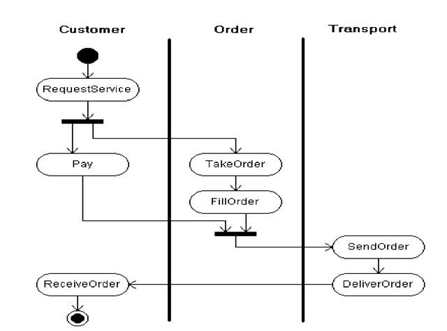
Figure 7 shows a typical UML activity diagram for a simple ordering process. The operations are represented in the ovals and the arrows show the cause and effect scenario or the “triggers”. In this diagram, there are two “fork/join” model elements, and the use of “conditional branch states” is also common. Each of the operations must be associated with a particular object type. The standard way to do that in this UML type diagram is to use “swimlanes”, and these are the vertical lines shown in Figure 7.
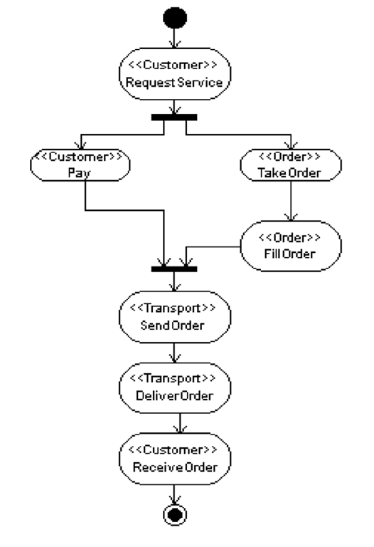
There are two problems with the standard representation as shown in Figure 7. The first problem is that, as the system gets more complex (more object types and operations), it is very difficult to draw in swimlanes. The second problem is that code generation is very difficult in UML CASE products since you have to scan the geometry of the drawing to find out which operations lay in which swimlanes. A solution to the above problems with standard UML activity diagrams is to use a stereotype for the operation element to indicate the object type (class) owning that operation. Figure 8 shows the same systems as Figure 7 drawn with the “operation owner” stereotype.
Figure 7.
Figure 8.
Model Consistency
The use of these UML stereotypes allows a greater degree of consistency checking of business models. A final business system design will involve several UML diagram types. For example business systems typically have static structural diagrams (UML Class Diagram) and dynamic diagrams (UML Activity Diagram). These diagrams must be consistent with one another, in particular:
1. The object types (shown with the operation stereotype notation) that contain the operations in activity diagrams must be included on the structural diagrams.
2. The operations shown in the activity diagrams (along with the object types identified with the stereotype notation) must be included as operations in the same object type on the structural diagrams.
For a UML business system example (including implementation in C++), the reader is referred to the full topic chapter on this subject (Brandon, 2003).
FUTURE TRENDS
As UML becomes more accepted for general use in the design of business systems, we could expect to see more universal stereotypes being formulated. Eventually, libraries of these stereotypes should become generally available and UML tool vendors would include support for these libraries in their products.
CONCLUSION
UML stereotypes can be very useful in designing business systems. For example, the use of a “relationship” stereotype is helpful in static structural models (UML Class Diagrams) and the use of an “operation owner” stereotype is most helpful in dynamic models (UML Activity Diagrams). These stereotypes aid in both the design/drawing phase and in the implementation (coding) phase of the overall system construction.
KEY TERMS
Activity Diagram: An UML diagram showing operations and triggers between operations; a diagram which shows system dynamics via cause and effect relationships. An activity diagram is a state diagram in which most of the states are action states, and most of the transitions are triggered by the completion of these action states.
CASE: Computer Aided Software Engineering.
Class: A program construct representing a type of thing (abstract data type) which includes a definition of both form (information or data) and functionality (methods); the implementation of the design concept of “object type”.
Composition: A new class in an objected programming language that is composed of other classes.
Dynamic Model: A UML model describing dynamic behavior such as state changes, triggers, and object type operations.
Encapsulation: The ability to insulate data in a class so that both data security and integrity is improved.
Framework: A software foundation which specifies how a software system is to be built. It includes standards at all levels both internal construction and external appearance and behavior.
Function: A programming construct where code that does a particular task is segregated from the main body of a program; the function may be sent arguments and may return arguments to the body of the program.
Implementation: The code placed inside of methods. For some languages, this code is pre-compiled or interpreted.
Include: Some code stored separately from the main body of a program, so that this code can be used in many programs (or multiple places in the same program).
Inheritance: A feature of object-oriented languages that allow a new class to be derived from another class (a more general class); derived classes (more specific classes) inherit the form and functionality of their base class.
Interface: The specification for a method (“what” a method does); how that function is called from another program. Interfaces are provided in source form as opposed to implementations which are secure. This allows one to use a method without regard for “how” that method is coded. It also allows multiple implementations of the same interface.
Libraries: A group of functions and/or classes stored separately from the main body of the main program; an “include” file consisting of functions and/or classes.
Metaclass: A class whose instances are classes.
Method: A function defined inside of a class, a processing specification for an operation.
Object Type: A specification of a type of entity, both structure (attributes) and operations (functions) are specified for object types; the notion of object type is a design notion being implemented as a “class”.
Operation: A process related notion in UML; operations cause state changes in objects.
Packages: Similar to a library, but just containing classes.
Patterns: A software library for a common business scenario. A framework may be a design framework (possibly expressed in UML [Unified Modeling Language]) or an implementation framework (possibly in C++, Java, or PHP).
Polymorphism: The ability of object-oriented programs to have multiple implementations of the same method name in different classes in an inheritance tree. Derived classes can override the functionality defined in their base class.
Relationship: A connection concept between object types. There are several types of relationships including: aggregation, composition, association, and inheritance (generalization/specialization).
Reuse: Reuse (software) is a process where a technology asset (such as a function or class) is designed and developed following specific standards, and with the intent of being used again.
Separation: The separation of what a method does (interface) from how the method does it (implementation).
Stereotype: The core extension mechanism of UML.
Structural Model: An UML model describing static structure (relationships and properties).
Trigger: One operation invoking another operation; a call from one method to another method within the same or different object type (class).
UML: Unified Modeling Language
