8.2
The basic premises and principles of the Direct Torque Control (DTC) method, proposed by Takahashi and Noguchi in 1986, can be formulated as follows:
• Stator flux is a time integral of the stator EMF. Therefore, its magnitude strongly depends on the stator voltage.
• Developed torque is proportional to the sine of angle between the stator and rotor flux vectors.
• Reaction of rotor flux to changes in stator voltage is slower than that of the stator flux.
Consequently, both the magnitude of stator flux and the developed torque can be directly controlled by proper selection of space vectors of stator voltage, that is, selection of consecutive inverter states. Specifically:
• Nonzero voltage vectors whose misalignment with the stator flux vector does not exceed ±90° cause the flux to increase.
• Nonzero voltage vectors whose misalignment with the stator flux vector exceeds ±90° cause the flux to decrease.
• Zero states, 0 and 7, (of reasonably short duration) practically do not affect the vector of stator flux which, consequently, stops moving.
• The developed torque can be controlled by selecting such inverter states that the stator flux vector is accelerated, stopped, or decelerated.
![tmp323-95_thumb[2] tmp323-95_thumb[2]](http://lh6.ggpht.com/_X6JnoL0U4BY/S1h8-xrGAuI/AAAAAAAAIX4/Zz8wmfIYyJQ/tmp32395_thumb2_thumb.png?imgmax=800)
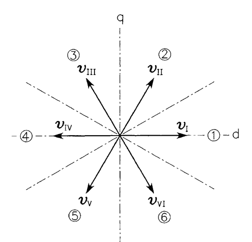
FIGURE 8.3 Space vectors of the inverter output voltage and sectors of the vector plane.
![tmp323-97_thumb[1] tmp323-97_thumb[1]](http://lh5.ggpht.com/_X6JnoL0U4BY/S1h-jVSbujI/AAAAAAAAIYI/BTG6VTIZa50/tmp32397_thumb1_thumb.png?imgmax=800)
TABLE 8.1 Impact of Individual Voltage Vectors on the Stator Flux and Developed Torque

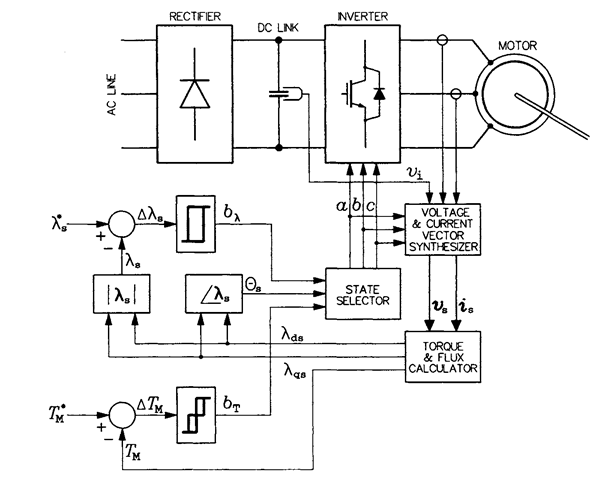
FIGURE 8.4 Block diagram of the DTC drive system.
![tmp323-100_thumb[1] tmp323-100_thumb[1]](http://lh5.ggpht.com/_X6JnoL0U4BY/S1h-_ZE7PMI/AAAAAAAAIYg/Iy6Oj_VeuGI/tmp323100_thumb1_thumb.png?imgmax=800)

FIGURE 8.5 Characteristics of: (a) flux controller, (b) torque controller.
TABLE 8.2 Selection of the Inverter State in the DTC Scheme; (a) Counterclockwise Rotation
| h | 1 | 0 | ||||
| by | 1 | 0 | -1 | 1 | 0 | -1 |
| Sector 1 | 6 | 7 | 5 | 2 | 0 | 1 |
| Sector 2 | 2 | 0 | 4 | 3 | 7 | 5 |
| Sector 3 | 3 | 7 | 6 | 1 | 0 | 4 |
| Sector 4 | 1 | 0 | 2 | 5 | 7 | 6 |
| Sector 5 | 5 | 7 | 3 | 4 | 0 | 2 |
| Sector 6 | 4 | 0 | 1 | 6 | 7 | 3 |
| (b) Clockwise Rotation | ||||||
| K | 1 | 0 | ||||
| by | 1 | 0 | -1 | 1 | 0 | -1 |
| Sector 1 | 5 | 7 | 6 | 1 | 0 | 2 |
| Sector 2 | 1 | 0 | 4 | 3 | 7 | 6 |
| Sector 3 | 3 | 7 | 5 | 2 | 0 | 4 |
| Sector 4 | 2 | 0 | 1 | 6 | 7 | 5 |
| Sector 5 | 6 | 7 | 3 | 4 | 0 | 1 |
| Sector 6 | 4 | 0 | 2 | 5 | 7 | 3 |

FIGURE 8.6 Illustration of the principles of inverter state selection.
flux and torque are to be decreased; (2) the flux is to be decreased, but the torque is to be increased; (3) the flux is to be increased, but the torque is to be decreased; (4) both the flux and torque are to be increased; and (5) the torque error is within the tolerance range. In Cases (1) to (4), appropriate nonzero states are imposed, while Case (5) calls for such a zero state that minimizes the number of switchings (State 0 follows States 1, 2, and 4, and State 7 follows States 3, 5, and 6).
To illustrate the impact of the flux tolerance band on the trajectory of A.s, a wide and a narrow band are considered, with bT assumed to be 1. The corresponding example trajectories are shown in Figure 8.7. Links between the inverter voltage vectors and segments of the flux trajectory are also indicated. Similarly to the case of current control with hysteresis

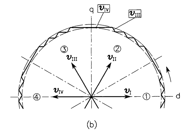
FIGURE 8.7 Example trajectories of the stator flux vector (bT = 1): (a) wide error tolerance band, (b) narrow error tolerance band.
controllers (see Section 4.5), the switching frequency and quality of the flux waveforms increase when the width of the tolerance band is decreased.
The only parameter of the motor required in the DTC algorithm is the stator resistance
, Rs, whose accurate knowledge is crucial for high-performance low-speed operation of the drive. Low speeds are accompanied by a low stator voltage (the CVH principle is satisfied in all ac ASDs), which is comparable with the voltage drop across Rs. Therefore, modern DTC ASDs are equipped with estimators or observers of that resistance. Various other, improvements of the basic scheme described, often involving machine intelligence systems, are also used to improve
the dynamics and efficiency of the drive and to enhance the quality of stator currents in the motor. An interesting example of such an improvement is the “sector shifting” concept, employed for reducing the response time of the drive to the torque command. It is worth mentioning that this time is often used as a major indicator of quality of the dynamic performance of an ASD.
As illustrated in Figure 8.8,
a vector of inverter voltage used in one sector of the vector plane to decrease the stator flux is employed in the next sector when the flux is to be increased. With such a control and with the normal division of the vector plane into six equal sectors, the trajectory of stator flux vector forms a piecewise-linear approximation of a circle. Figure 8.9 depicts a situation in which, following a rapid change in the torque command, the line separating Sectors 2 and 3 is shifted back by a radians. It can be seen that the inverter is “cheated” into applying vectors vv and vIV instead of Vjy and vra, respectively. Note that the linear speed of travel of the stator flux vector along its trajectory is constant and equals the dc supply voltage of the inverter. Therefore, as that vector takes now a “shortcut,” it arrives at a new location in a shorter time than if it traveled along the regular trajectory. The acceleration of stator flux vector described results in a rapid increase of the torque, because that vector quickly moves away from the rotor flux vector. The greater the sector shift, a, the greater the torque increase. It can easily be shown (the reader is encouraged to do that) that expanding a sector, that is shifting its border forward (a < 0), leads to instability as the flux vector is directed toward the outside of the tolerance band.
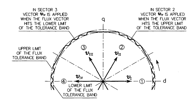
FIGURE 8.8 Selection of inverter voltage vectors under regular operating conditions.

FIGURE 8.9 Acceleration of the stator flux vector by sector shifting.
To highlight the basic differences between the direct field orientation (DFO), indirect field orientation (IFO), and DTC schemes, general block diagrams of the respective drive systems are shown in Figures 8.10 to 8.12. The approach to inverter control in the DFO and IFO drives is distinctly different from that in the DTC system. Also, the bang-bang hysteresis controllers in the latter drive contrast with the linear flux and torque controllers used in the field orientation schemes.
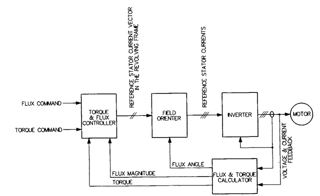
FIGURE 8.10 Simplified block diagram of the direct field orientation scheme.
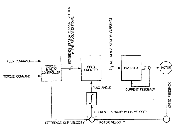
FIGURE 8.1 I Simplified block diagram of the indirect field orientation scheme.
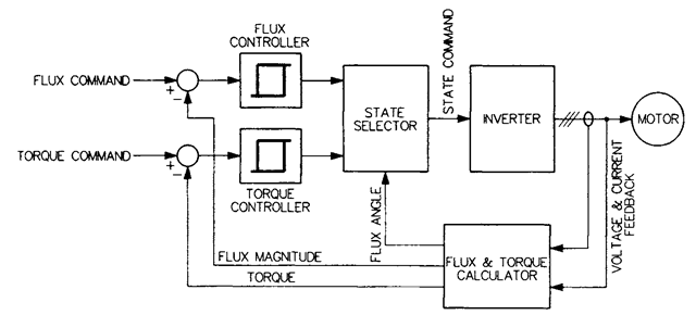
FIGURE 8.12 Simplified block diagram of the DTC scheme.
