4.6
Current source inverters are less commonly used in induction motor ASDs than voltage source inverters, mostly due to the poorer quality of output currents. Still, they have certain advantages, such as imperviousness to overcurrents, even with a short circuit in the inverter or the load. The absence of freewheeling diodes further increases the reliability. Also, current source inverters are characterized by inherently excellent dynamics of the phase angle control of the output current. Such control is realized by changing the state of inverter and the resultant redirecting of the source current. However, the magnitude adjustments of output currents can only be performed in the supplying rectifier. The rectifier allows bidirectional flow of power, and, because the input current is always positive, the input voltage becomes negative when the power flows from the load to the supply power system. Therefore, semiconductor power switches used in a current source inverter must have the reverse blocking capability.
In contrast with voltage source inverters,
the simultaneous on-state of both switches in the same inverter leg is safe and recommended for a short period of time initiating a state change of the inverter. This is to avoid the danger of interrupting the current, which would result in an overvoltage. Consequently, switching variables are defined differently than those in the voltage source inverter. In the subsequent considerations, variables a, b, and c are assigned to switches SA, SB, and SC (e.g., a — 1 means that SA is on), and variables a’, b’, and c’ to switches SA’, SB’, and SC (see Figure 4.14). Then, the output line currents, iA, iB, and ic, of the current source inverter can be expressed as
![tmp2F3-62_thumb[1] tmp2F3-62_thumb[1]](http://lh4.ggpht.com/_X6JnoL0U4BY/S1hsA874F9I/AAAAAAAAIKY/_Z4r9TYbLUU/tmp2F362_thumb1_thumb.png?imgmax=800)
where I{ denotes the constant input current. If the motor has a delta-connected stator, then the currents, iAB, /BC, and i’CA, in the individual phase windings are given by
![tmp2F3-63_thumb[1] tmp2F3-63_thumb[1]](http://lh6.ggpht.com/_X6JnoL0U4BY/S1hsCRYcu0I/AAAAAAAAIKg/fLnTWKZUaVU/tmp2F363_thumb1_thumb.png?imgmax=800)
The peak value of the fundamental line currents is approximately 1.1
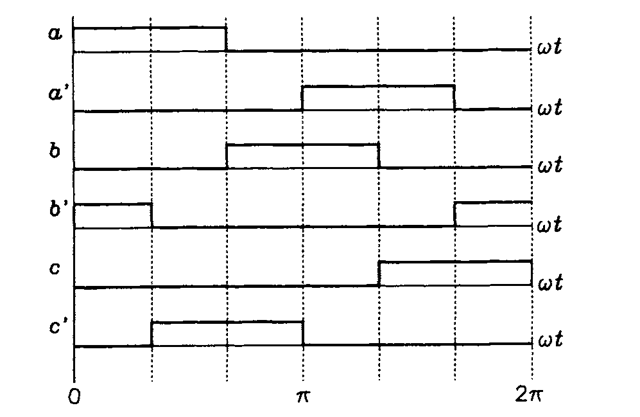
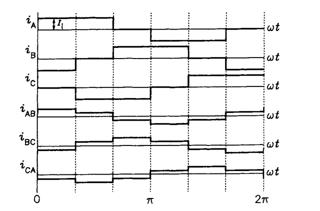
Switching variables in the square-wave operation mode of the current source inverter are shown in Figure 4.31 and the resultant output current waveforms in Figure 4.32. It can be seen that at any time only two switches

FIGURE 4.31 Switching variables in the current source inverter in the square-wave operation mode.

FIGURE 4.32 Output current waveforms in a current source inverter in the square-wave operation mode.
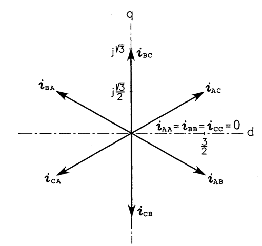
conduct the output currents. This conduction pattern is typical for the voltage source rectifier which, indeed, is an inverse of the current source inverter. Space vectors of the line currents associated with individual states of the inverter are depicted in Figure 4.33 in the per-unit format, with the dc input current, /j, taken as the base current. The states are designated by letters denoting conducting switches of the inverter. For example, State AB represents the situation in which the conducting switches are SA and SB’. Simultaneous conduction of both switches in the same leg results in a zero vector (States AA, BB, and CC).
Similarly to the voltage source inverter, the square-wave mode of operation requires each switch to be turned on and off once per cycle only. This is one of the reasons that current source inverters have typically been used in high-power drives, with large and slow semiconductor power switches employed in the inverter.
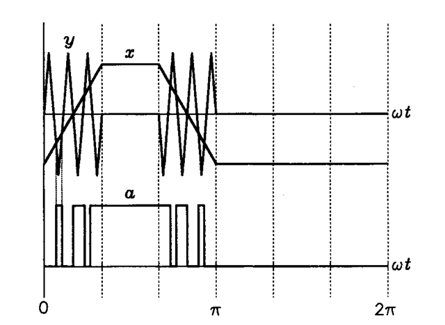
PWM current source inverters, equipped with output capacitors (see Figure 4.14), are characterized by significantly higher quality of output currents than that in square-wave inverters. Several PWM techniques have been developed, one of them, based on a trapezoidal modulating function, illustrated in Figure 4.34. The modulating function signal, x, is compared with a triangular carrier signal, y, and the intersection instants determine

FIGURE 4.33 Space vectors of the line currents (per unit) in the current source inverter.

FIGURE 4.34 Illustration of a PWM technique for a current source inverter.
the value of switching variable a. With respect to a, switching variables b and c are delayed by one-third and two-thirds of the period of output current. Variables a’,b’, and c’ are shifted with respect to a, b, and c by a half period. The best attenuation of low-order harmonics in the output currents is achieved with the peak value of the modulating function equal 0.82 of the peak of the carrier signal. PWM current source inverters are not feasible for high-power drives because of the excessive size of the required capacitors.
