5.3
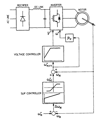
With the motor speed measured or estimated, it can be controlled in the closed-loop scheme shown in Figure 5.7. The speed (angular velocity), coM, is compared with the reference speed, (Ojjjj. The speed error signal, AcoM, is applied to a slip controller, usually of the PI (proportional-integral) type, which generates the reference slip speed, co*!. The slip speed must be limited for stability and overcurrent prevention. Therefore, the slip controller’s static characteristic exhibits saturation at a level somewhat lower than the critical slip speed. When co*! is added to o)M, the reference synchronous speed, w*yn, is obtained. As in the CVH drives in Figures 5.5 and 5.6, the latter signal used to generate the reference values, w* and V*, of the inverter frequency and voltage.
In conjunction with the widespread application of the space vector PWM techniques described in Section 4.5, it is the reference vector, v* = V*e&*, of the inverter output voltage that is often produced by the control system. Strictly speaking, the control system determines the reference values m* of the modulation index and 0* of the voltage vector angle, because these two variables are needed for calculation of duty ratios of inverter states within a given switching interval. Clearly, values

FIGURE 5.7 Scalar-controlled drive system with slip controller.
![tmp323-19_thumb[1] tmp323-19_thumb[1]](http://lh5.ggpht.com/_X6JnoL0U4BY/S1hvChj6yUI/AAAAAAAAIOQ/8IIq4ixHYCc/tmp32319_thumb1_thumb.png?imgmax=800)
