Robotics and Animation
This section is mainly intended as an example of frames and transformations and how the former can greatly facilitate the study of the latter, but it also enables us to give a brief introduction to the subject of the kinematics of robot arms. Even though we can only cover some very simple aspects of robotics here, we cover enough so that the reader will learn something about what is involved in animating figures.
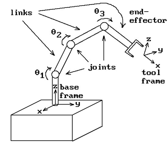
Figure 4.23. Robot arm terminology.
Mechanical manipulators are the most important examples of industrial robots and much work has been done to understand the mechanics and control of such manipulators. We begin with some terminology (see [Crai89]).
Kinematics: The science of motion where motion is studied without worrying about what caused it.
Manipulator: This is assumed to be an object that consists of nearly rigid links connected by joints that allow neighboring links to move. One end is usually fixed to some nonmoving part and the other end is free. See Figure 4.23. The joints may be either revolute joints, which allow rotational motion measured by joint angles, or prismatic joints, which allow sliding motion that is measured by joint offsets.
Degrees of freedom of a manipulator: This is the number of variables that it takes to completely describe the state or position of the manipulator. Typically this is the number of joints since joints can usually be described by one variable.
End-effector: This is the tool at the free end of the manipulator such as a gripper.
Tool frame: The frame associated to the end-effector.
Base frame: The frame associated to the fixed end of the manipulator.
Forward kinematics: This is the problem where one wants to compute the tool frame (intuitively, the position and orientation of the tool) relative to the base frame given the set of joint angles.
Inverse kinematics: This is the problem where one wants to compute all possible sets of joint angles that can give rise to given tool and base frames. This problem is usually more difficult than the forward kinematics problem. There may not even be a solution to a particular problem or there may be more than one solution.
Workspace for a given manipulator: The possible tool frames (position and orientation of the tool) that are achievable by the manipulator.
Trajectory generation: The determination of the trajectories of each joint of a manipulator that lead from some initial configuration to a final configuration. Since manipulators are usually moved by actuators that apply a force or torque to each joint, these forces and torques would also have to be computed in order for a solution to be effective.
For all practical purposes, links will be treated as rigid bodies connecting joints. Links will be numbered starting with link number 0 at the base. Joints will also be numbered with joint number i being the joint between link number i – 1 and i. The ith joint can be defined by an axis Li about which the joint rotates or along which it slides. Define the link length a, to be the distance between the axes Li and![]() and let pi be the point on Lj and
and let pi be the point on Lj and![]() the point on
the point on![]() so that
so that![tmpc646696_thumb[2][2][2][2] tmpc646696_thumb[2][2][2][2]](http://what-when-how.com/wp-content/uploads/2012/06/tmpc646696_thumb2222_thumb.png) The points pi and qi are always unique except in the case where axes are parallel. Since the choice of these points is only an issue in defining the initial configuration of a manipulator, we can either disallow this case or assume that they have been picked appropriately in some other manner. We assume that all the ai are nonzero. Next associate a link frame
The points pi and qi are always unique except in the case where axes are parallel. Since the choice of these points is only an issue in defining the initial configuration of a manipulator, we can either disallow this case or assume that they have been picked appropriately in some other manner. We assume that all the ai are nonzero. Next associate a link frame ![]() to the ith link as follows:
to the ith link as follows:
(1)![]() is a direction vector for
is a direction vector for![]() that is, it is parallel to the ith joint axis,
that is, it is parallel to the ith joint axis,
(2)![]() is the unit vector in the direction ’
is the unit vector in the direction ’![]() _ and
_ and
(3)![]() so that the ordered basis
so that the ordered basis![]() determines the standard orien
determines the standard orien
tation of R3.
Define the link twist Oj to be the angle between![]() and choose the sign of the angle to be positive or negative depending on whether or not the ordered bases
and choose the sign of the angle to be positive or negative depending on whether or not the ordered bases![]() and
and![]() determine the same orientation in the
determine the same orientation in the![]() plane of Fj (this corresponds to
plane of Fj (this corresponds to
using the right hand rule for angles about the![]() ). Define the joint offset
). Define the joint offset![]() by
by
![]() Note that
Note that![]() is the distance between ’
is the distance between ’![]() is a variable if the joint is prismatic. Finally, define the joint angle
is a variable if the joint is prismatic. Finally, define the joint angle![]() to be the signed angle between
to be the signed angle between![]() This is a variable if the joint is revolute. The quantities
This is a variable if the joint is revolute. The quantities![]() are called the link parameters. All, except a^, are signed numbers. See Figure 4.24.
are called the link parameters. All, except a^, are signed numbers. See Figure 4.24.
There are some special cases at the ends of the manipulator. Assume that there are n + 1 links. It is convenient to choose Fo to be the same as Fi when![]() is zero. At the other end there are two cases. If the last joint is revolute, then
is zero. At the other end there are two cases. If the last joint is revolute, then![]() is set equal to
is set equal to ![]() is zero. If the joint is prismatic, then xn is set equal to
is zero. If the joint is prismatic, then xn is set equal to![]() The point
The point![]() is always set equal to
is always set equal to![]()
The robot or manipulator is completely described in one of two ways. We can either specify the link frames Fi or we can specify the list of link parameters![tmpc646733_thumb[2][2][2][2] tmpc646733_thumb[2][2][2][2]](http://what-when-how.com/wp-content/uploads/2012/06/tmpc646733_thumb2222_thumb.png) and
and![]() Our discussion above basically showed how the latter are derived from the former.
Our discussion above basically showed how the latter are derived from the former.
Figure 4.24. The geometry of links.
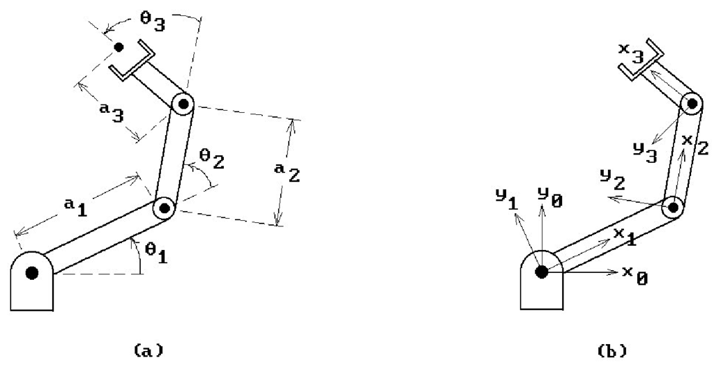
Figure 4.25. Two-dimensional robot arm geometry.
One can also show that the link parameters completely define the frames. In practice it is easier for a user to manipulate the link parameters and so the usual problem is to find the frames given their values. As another example, consider a two dimensional robot with three links and revolute joints. We can think of this as a special case of the general one where all the z-axes of the frames point in the same direction and all the ai and di are zero. Figure 4.25(a) shows the link parameters and Figure 4.25(b), the associated frames.
As one can see, frames play a role in defining the state of a robot, but how are they used to solve problems? Well, the forward kinematic problem is to find the tool frame (“where the tool is”) given the link parameters. This problem will be solved if we can determine the transformation Tn, which, given the coordinates of a point p in Fn coordinates, finds the coordinates of p with respect to F0. Let![]() denote the transformation that maps coordinates relative to Fi to coordinates relative to Fi-1. It follows that
denote the transformation that maps coordinates relative to Fi to coordinates relative to Fi-1. It follows that
The dTi are relatively easy to compute from the link parameters because they are the composition of four simple maps.
The Computation of dTi and Its Homogeneous Matrix dMi. Let![]() denote the translation with translation vector dizi. Its homogeneous matrix is
denote the translation with translation vector dizi. Its homogeneous matrix is
Let![tmpc646763_thumb[2][2][2][2] tmpc646763_thumb[2][2][2][2]](http://what-when-how.com/wp-content/uploads/2012/06/tmpc646763_thumb2222_thumb.png) denote the rotation about the
denote the rotation about the![]() axis of the frame
axis of the frame![]() through an angle
through an angle![]()
Its homogeneous matrix is
Let![]() denote the translation with translation vector
denote the translation with translation vector![tmpc646773_thumb[2][2][2][2] tmpc646773_thumb[2][2][2][2]](http://what-when-how.com/wp-content/uploads/2012/06/tmpc646773_thumb2222_thumb.png) Its homogeneous matrix is
Its homogeneous matrix is
Finally, let![]() denote the rotation about the
denote the rotation about the![]() axis of the frame
axis of the frame![tmpc646779_thumb[2][2][2][2] tmpc646779_thumb[2][2][2][2]](http://what-when-how.com/wp-content/uploads/2012/06/tmpc646779_thumb2222_thumb.png) through an angle
through an angle![]() Its homogeneous matrix is
Its homogeneous matrix is
Then
and multiplying the matrices for the corresponding maps together (but in reverse order since matrices act on the right of a point), we get that the matrix dMi associated to the transformation dTi is defined by
Equations (4.21-4.23) provide the solution to the forward kinematic problem. In the two-dimensional robot case where![tmpc646788_thumb[2][2][2][2] tmpc646788_thumb[2][2][2][2]](http://what-when-how.com/wp-content/uploads/2012/06/tmpc646788_thumb2222_thumb.png) are zero, the matrices
are zero, the matrices![tmpc646789_thumb[2][2][2][2] tmpc646789_thumb[2][2][2][2]](http://what-when-how.com/wp-content/uploads/2012/06/tmpc646789_thumb2222_thumb.png) specialize to matrices dNi, where
specialize to matrices dNi, where
This concludes what we have to say about robotics. For a more in-depth study of the subject see [Crai89], [Feat87], or [Paul82]. The description of mechanical manipulators in terms of the four link parameters described in this section is usually called the Denavit-Hartenberg notation (see [DenH55]).
As is often the case when one is learning something new, a real understanding of the issues does not come until one has worked out some concrete examples. The animation programming projects 4.13.1 and 4.13.2 should help in that regard. Here are a few comments about how one animates objects. Recall the discussion in Section 2.11 for the 2d case. To show motion one again discretizes time and shows a sequence of still pictures of the world as it would look at increasing times![]() One changes the apparent speed of the motion by changing the size of the time intervals between
One changes the apparent speed of the motion by changing the size of the time intervals between![]() ‘ the larger the intervals, the larger the apparent speed. Therefore, to move an object X, one begins by showing the world with the object at its initial position and then loops through reshowing the world, each time placing the object in its next position.
‘ the larger the intervals, the larger the apparent speed. Therefore, to move an object X, one begins by showing the world with the object at its initial position and then loops through reshowing the world, each time placing the object in its next position.


![tmpc646762_thumb[2][2][2][2] tmpc646762_thumb[2][2][2][2]](http://what-when-how.com/wp-content/uploads/2012/06/tmpc646762_thumb2222_thumb.png)
![tmpc646771_thumb[2][2][2][2] tmpc646771_thumb[2][2][2][2]](http://what-when-how.com/wp-content/uploads/2012/06/tmpc646771_thumb2222_thumb.png)
![tmpc646776_thumb[2][2][2][2] tmpc646776_thumb[2][2][2][2]](http://what-when-how.com/wp-content/uploads/2012/06/tmpc646776_thumb2222_thumb.png)
![tmpc646785_thumb[2][2][2][2] tmpc646785_thumb[2][2][2][2]](http://what-when-how.com/wp-content/uploads/2012/06/tmpc646785_thumb2222_thumb.png)
![tmpc646787_thumb[2][2][2][2] tmpc646787_thumb[2][2][2][2]](http://what-when-how.com/wp-content/uploads/2012/06/tmpc646787_thumb2222_thumb.png)
![tmpc646792_thumb[2][2][2][2] tmpc646792_thumb[2][2][2][2]](http://what-when-how.com/wp-content/uploads/2012/06/tmpc646792_thumb2222_thumb.png)
