Rotary Engines
During the history of the automobile engines, efforts have been made to replace
the conventional reciprocating motion of the pistons by one of rotation. Only two
types of rotary engines have been successful as automobile engines. One is the
rotating combustion chamber engine (Wankel engine) and the other is the turbine.
The basic design of the modern Wankel rotary piston engine was established in
1957. The development of the engine in the present form is due to two German
engineers, F. Wankel and W. Froede, as a result of many years of fundamental work
carried by the former.
The application of the gas turbine to the smaller types of road vehicle is due to
the successful enterprise of the Rover Company in the 1963 and subsequently by Le
Mans in the 1965. The chapter discusses the basics of these two engines.
5.1.
Wankel Engines
5.1.1.
Principle of Operation
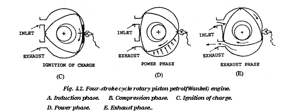
The Wankel engine (Fig. 5.1) uses of a piston of triangular form, which turns with an
eccentric motion within a chamber of approximately figure-of-eight shape, embodied in a
stationary housing. The piston rotates upon an eccentric output shaft and is provided with side
and apex seals that maintain continuous contact with the working surfaces of the chamber. The
gas porting arrangements and the sparking plugs are located on opposing sides and adjacent to
the minor axis of this chamber. As the piston rotates, it develops three small chambers of
constantly changing volume. The induction, compression, power and exhaust phases of the
rotary piston petrol engine operating on four-stroke cycle is illustrated in Fig. 5.2 A, through E.
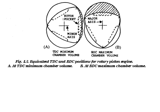
The position of minimum and maximum volumes of each chamber occur at the minor and
the major axes of the chamber respectively, and correspond to the TDC and BDC positions of
the reciprocating piston engine. These positions are illustrated in Fig. 5.3 A and B.
In the power phase, the combustion pressure acting upon the projected area of the piston
flank imparts a turning moment or torque to the output shaft. The resultant force of the
combustion pressure acts through the centroid of the piston at the distance of the eccentric throw
(Fig. 5.4).
Since the piston not only rotates about its own axis, but also rotates eccentrically about the
centroid of the working chamber, a system of internal phasing gears is required to maintain
correct orbital motion of the piston throughout its operating cycle (Fig. 5.5). As a consequence,

Fig. 5.1. Two-rotor Wankel engine.
the piston performs three complete revolutions of the eccentric output shaft upon which the
piston rotates, and hence the engine completes three four-stroke cycles. Therefore, a rotary
piston engine delivers a power impulse for every revolution of its output shaft, as compared to
every two revolutions of the crankshaft in a reciprocating piston engine working on four-stroke
cycle. Thus a single-piston rotary engine is equivalent to a twin-piston reciprocating engine. As
a result, a rotary engine occupies less space and offers a reduction in weight when compared
with the reciprocating engine of same power output.

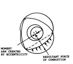 |
Fig. 5.4. Torque or running effort.
5.1.2.
Construction Details
Wankel engines with up to four pistons have
been developed for passenger car applications,
although current production engines have two
pistons (often referred to as twin-rotor engines).
The basic construction comprises an eccentric
output shaft, rotor assemblies and phasing
gears.
Eccentric Output Shaft.
The eccentric output shaft in the rotary en-
gine is the equivalent component to the
crankshaft of the reciprocating engine, and is
made from one-piece steel with the eccentric
journals diametrically opposed to provide even
firing intervals (Fig. 5.6). The output shaft jour
![clip_image002[5] clip_image002[5]](http://lh5.ggpht.com/_Ii1ukGkfijY/SqqXVWs5TfI/AAAAAAAADno/w9vh7VCQHL0/clip_image0025_thumb.jpg?imgmax=800) |
nal eccentricity corresponds to the crank
throw radius of a conventional crankshaft. In
twin-rotor engines, the stiffness of the output
shaft is sufficient for its required support in
only two main end bearings, although high
output versions may require an intermediate
bearing.
Apart from the gas loading applied
through the rotor, the centrifugal force acting
upon each eccentric journal and rotor assemb-
ly also tends to deflect the shaft. The deflec-
tion must be resisted by the main bearings,
and their loading can be correspondingly
reduced by the introduction of a simple sys-
tem of counter weighting. Counterbalance
‘ lg&t ‘ weights are either formed integrally with the
flywheel and the front pulley, or as a combination of counter-weighted flywheel and separately
attached front counterweight.
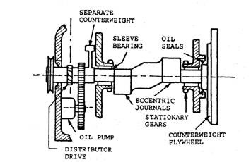 |
Fig. 5.6. Eccentric output shaft assembly.
One or more gears are also mounted on the nose portion of the output shaft to drive the oil
pump and the ignition distributor. The method of fixing these components on the output shaft
is similar to that for a reciprocating engine crankshaft assembly. The flywheel is attached to
the rear end of the output shaft using either a spigot or a taper method of retention. Sleeve type
main bearings are employed on to each end of the output shaft and are of similar composite
construction to the thin walled half-liners, which support a conventional crankshaft. The sleeve
bearings are retained by interference fit in the central bore of each of the stationary phasing
gears, which in turn are mounted through the front and rear end covers of the engine. If an
intermediate bearing is used, it must of course be divided in a plane containing the axis of the
output shaft for the assembly to be possible. Endwise retention of the output shaft is obtained
by either having a plain collar with rolling contact, or thrust bearings. Conventional radial lip
type seals are used at each end of the output shaft.
Rotor Assembly.
The rotary piston (or rotor) assembly takes the form of an equilateral triangle with convex
flanks, and their actual profile is related to the geometry of the operating chamber. The rotor
generally is of a box-section construction with internal ribbing and is made from cast iron for
durability. The flanks of the rotor are pocketed to form part of the moving combustion chamber
and to assist gas transfer across the minor axis of the rotor chamber (Fig. 5.3). Each rotor uses
a sleeve bearing of the type used to support the output shaft main journals.
Phasing Gear.
An internally toothed phasing gear is recessed into the outer side of each rotor and is
retained both axially and rotationally by using a ring of spring pins. These gears mesh with the
stationary phasing gears and provide the necessary speed ratio of 1:3 between the rotors and
the output shaft.
Seals.
The gas and oil sealing arrangement for the rotor is relatively complex. The gas sealing of
the rotor in its operating chamber is accomplished by the arrangement called the sealing grid.
This essentially contains three apex seals positioned radially in trunnion blocks, which are
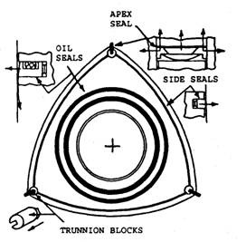 |
Fig. 5.7. Rotor sealinggrid details.
connected by curved sealing strips located in slots on each slide of the rotor (Fig. 5.7).
Similar to the conventional piston rings, the
rotor seals are spring loaded against their work-
ing surfaces to provide initial sealing pressure,
which is then greatly increased by chamber gas
pressure acting behind them once the engine has
started. Again as with piston ring, the required
sealing pressures are obtained partly from the
small contact area conffered by the narrow
working surfaces of the seal elements. Unlike
the piston ring, however, the orbital motion of
the rotor results in appreciable tilting of its apex
seals as they sweep between the major and the
minor axes of the operating chamber. The apex
seals are the most critical elements of the sealing
grid and currently a three-piece construction for
each is employed. This has a centre section with
mitre-fitting end pieces, so that sealing pressure
is exerted in both radial and axial directions
(Fig. 5.7).
The apex seals are made from special metallic materials and hard carbon. Cast-iron piston
ring material is employed for the construction of the curved sealing strips, which bridge the
apex seals. This material is also used for the rotor oil control rings, which are taper faced and
seal against either the eccentric bearing, or the rotor chamber side walls. These seals prevent
rotor oil from passing into the combustion space while the engine is running and also from
draining into it when the engine is stopped.
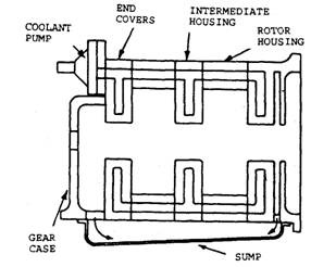 |
fig. 5.8. Housing and covers
Rotor Engine Housing and Covers.
The twin-rotor engine is built up in the man-
ner of a double-bank sandwich. It uses two rotor
housings and an intermediate housing, which
are flanked by front and rear end covers (Fig.
5.8). These parts are positioned relative to one
another by dowels and clamped together by a
series of long through-bolts. The coolant pump is
attached to the front cover and below this is fixed
a gear casing. This casing provides an oil tight
enclosure for the oil pump and ignition dis-
tributor drives, as well as accommodates mount-
ing points for these components. The rear cover
is suitably formed in to a flange for mounting of
the transmission bell-housing. For rigidity, the
intermediate housing and end covers are usually
made from cast iron. A stationary phasing gear, which is spigotted and clamped through each
end cover, engages with the adjacent rotor internal gear. The rotor shaft sleeve bearings are
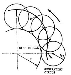 |
Fig. 5.9. Epitrochoidgeometry.
retained in the bores of the stationary phasing gears (Fig. 5.6) and are supported on the end
covers.
The main housing and the end covers are of a
double-skinned and internally ribbed construction.
This type of construction allows for the passage of
coolant either through or around them. The operat-
ing cycle of rotary engine is such that there exists a
hot zone un-cooled by the incoming mixture, which
occupies about three quarters of the working sur-
face. This gives rise to appreciable temperature
gradients around the rotor chamber. To minimize
the tendency of localized overheating, the rotor
housing is made of aluminium alloy. A wear resis-
tant coating is applied to the working surface of the
rotor chamber and may be either metallic or non-
metallic in character to complement the apex seal
material.
The geometric form of the operating chamber of the rotary engine, specifically the Wankel
engine, is defined as a two-lobed epitrochoid. This particular form is traced by a given point
within a generating circle as it rolls around the outside of a fixed base circle, the radius of the
letter being twice that of the former. In practice, the selected point is chosen at one-half the
radius of the generating circle (Fig. 5.9). The working surface of the rotor chamber is often
referred to as the epitrochoid surface.
5.1.3.
Lubrication System
A forced circulation lubrication system containing a conventional sump, oil pump, pressure
relief valve and oil filter, and additionally an oil cooler is used for the rotary piston engine. The
oil pump may be of either the external or the internal gear type. The pump is front mounted
four-stroke engine. Therefore peripheral intake and exhaust ports provide good breathing for
maximum power output. In compression, the incoming mixture is compelled to follow a less easy
path to reach side intake ports. These are necessarily sited in-board of the path swept by the
ends of the apex seals, and are instead opened and closed by the motion of the rotor side seals.
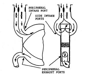 |
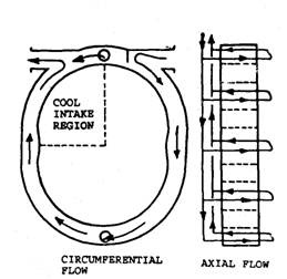 |
Fig. 5.11. Cooling of rotor housing. Fig. 5.12. Rotor chamber porting.
Side intake ports are always used in combination with a peripheral exhaust port and
physically limit the possible overlap in port timing to a very small amount. This arrangement
provides less dilution and loss of incoming charge at lower engine speeds with consequent
improvements in fuel consumption, part throttle performance and idling. However, this reduces
volumetric efficiency at high engine speeds. With twin-rotor engines it is customary to provide
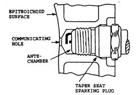 |
fig. 5.13. Spark plug location in rotary engine
a dual-exhaust system for minimum back pressure.
5.1.6.
Ignition-System
The air-fuel mixture is ignited by either a
single or dual spark plugs, which are positioned
opposite to the intake and exhaust ports and
adjacent to minor axis of the rotor chamber. The
compromise choice of either a single or dual
spark plugs or their location, relative to both the
epitrochoid surface and the minor axis of the
chamber, is dictated by the combustion charac-
teristics of the rotary engine. In this connection,
it is understood that the moving combustion
„. _ ,„ 0 , , , … ^ space lacks compactness, which is not conducive
. A ., . .
to rapid combustion and high efficiency.
Each tapered seat spark plug is screwed into an antechamber and communicates with the
combustion space, created by the rotor movement within its chamber, through a very small
diameter hole (Fig. 5.13). The purpose of this shielding is to minimize gas leakage past the apex
seals as they traverse the spark plug aperture. The spark plugs in rotary engines fire at twice
the frequency of those in a reciprocating four-stroke engine and do not receive any cooling effect
from the incoming mixture during the intake phase. These considerations require that the spark
plugs should have a very wide heat range, in order to avoid the two extremes of fouling at low
speeds and pre-ignition at high speeds.
