31.5.
Road Performance Curves: Acceleration, Gradability and Drawbar Pull
Passenger car performance is based on acceleration, ability to go up a slope, top speed, fuel economy, noise level, and durability. Transmission gearing is designed to provide maximum acceleration at low speed by holding the driving wheel torque output at the point of impending wheel spin. As wheel spin occurs, the acceleration decreases from the maximum. Also the gear is designed for maximum fuel economy when the engine is developing 80% of its maximum torque as the automobile is moving at a constant speed. This gives 20% additional torque for acceleration. The power required to drive an automobile increases as the cube of the speed i.e. it takes eight times the power to double the speed. When the power available matches the power required to push the vehicle, the speed becomes constant. Excess power is required for acceleration and hill climbing. Maximum speed is reached when there is no excess power remaining.
Figure 31.3 illustrates the variation of full-throttle power available at the wheels for four gear ratios with road speed. A curve, showing the power required by vehicle at various road speeds is also presented.
At any speed, the difference of ordinates of power available and power required by vehicle gives the surplus power, which can be utilized either for acceleration or for drawbar pull or for hill climbing. Or else the surplus power may be shared by all the three items as and when required.

Fig. 31.3. Road speed vs power available at wheels.
By using the formula given in section 31.3, the power available as indicated in Fig. 31.3 can be converted into tractive effort. Hence tractive effort performance curves for four gear ratios can be plotted against road speed as in Fig. 31.4. In this figure a road resistance curve is also presented. The difference between the ordinates of tractive effort and road resistance at any road speed gives the surplus tractive effort, which is utilized for acceleration, drawbar pull and hill climbing.

Fig. 31.4. Road speed vs tractive effort.
31.5.1.
Acceleration
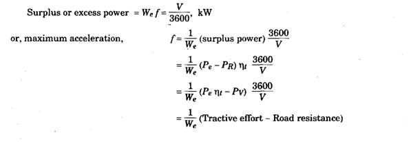
When the vehicle is accelerated, its rotating parts are also accelerated depending upon their moments of inertia and the gear ratio in the drive line. Due to this, weight of vehicle is increased from W to We. This increased weight, We, is called the ‘effective weight’ of the vehicle. When surplus power, i.e. surplus tractive effort is fully utilized to acceleration, then

![]()
31.5.2.
Gradability
The maximum percentage grade, which a vehicle can negotiate with full rated condition, is known as ‘gradability’. Hence,

31.5.3.
Drawbar Pull
When the excess power is fully utilized for pulling extra load attached to vehicle then,
Maximum drawbar pull = Tractive effort—Road resistance = (F— R).
Road resistance in this section is made up of rolling resistance and air resistance.
Figures 31.3 and 31.4 show that maximum surplus power and hence maximum surplus tractive effort are provided at very low speeds of the vehicle. Therefore, for acceleration from start, for climbing steeper gradient and for large drawbar pull, first gear is best suited.
Maximum road speed is achieved in the gear when power available equals to power required (Fig. 31.3) and tractive effort becomes equal to level road resistance (Fig. 31.4).
If the vehicle is desired to run at a lower speed, the throttle is adjusted accordingly so that the part throttle power available curve intersects the power required curve at the desired road speed. This is shown in Fig. 31.3.
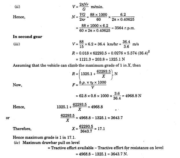
Example 31.1. The coefficient of rolling resistance for a truck weighing 62293,5 N is 0.018
2 2
and the coefficient of air resistance is 0.0276 in the formula R = KW + KqAV , N, where A is m of frontal area and V the speed in km i hr. The transmission efficiency in top gear of6.2:1 is 90%
and that in the second gear of 15:1 is 80%. The frontal area is 5.574 m . If the truck has to have a maximum speed of 88 km i hr in top gear calculate : (i) the engine b.p. required;
(ii) the engine speed if the driving wheels have an effective diameter of 0.8125 ni; (Hi) the maximum grade the truck can negotiate at the above engine speed in second gear; and
(iv) the maximum drawbar pull available on level at the above engine speed in second gear.


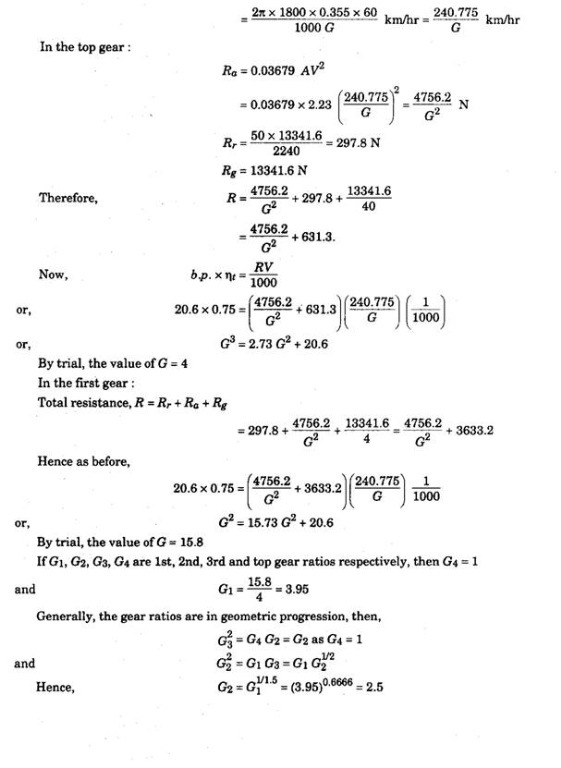
Example 31.2. Determine the gear ratios of a four speed gear box for a vehicle of weight 13341.6 Npowered by an engine giving 20.6 kW at 1800 r.p.m. The vehicle has a frontal area of 2.23 m and has a wheel dia 0.71 m. The maximum gradient that the car has to negotiate is 1 in 4. The tractive resistance may be taken as 50 N per 2240 N of the car. The wind resistance is
given by 0.03679 AV2, where A is the frontal area in m2 and V is the vehicle speed in km/hr. Assume that the transmission efficiency is 0.75 and that at top gear, the car is expected to go over a grade of 1 in 40. State any other assumptions you make.


