20.4.
Inspection
Inspection should always start with a good visual observation. If either premature or high-mileage failure has occurred, a visual inspection helps in evaluating the inter-relationship of the parts, so that corrective measures may be taken to prevent recurring failures. Parts are examined for wear patterns, scoring and pitting, foreign materials, and contamination. When abnormalities are observed, the mating parts should be thoroughly checked to find out the specific cause of failure.
The visual inspection is followed by dimensional checks. All parts are measured and their dimensions are compared to the manufacturer’s specifications for the engine. Specifications provide sizes and clearances. Parts either must be within specification tolerances or must be reconditioned to fall within the specification tolerances before they are reassembled. Parts that cannot be brought back to specifications are replaced.
Measuring Tools.
The basic measuring tool for an automotive technician is the micrometer, which is based on decimal divisions of a centimeter, reading to the nearest 0.01 mm. Automobile part specifications and clearances are given in this unit. Micrometers are usually used to measure external dimensions, and two common measurements are piston diameter and bearing journal diameter. However, some micrometers are designed to measure inside and depth dimensions, but these are not common in engine service.
The micrometer is based on divisions of the millimeter. The thread pitch in the micrometer determines the amount of movement of the spindle for each thimble revolution. In metric micrometers, one revolution of the thimble moves the spindle 0.5 mm. If the thimble is rotated one revolution, the edge of the thimble moves from one of the 0.5 mm subdivisions to the next. The edge of the thimble has 50 divisions, each representing a spindle movement of one fiftieth of a mm. To read a micrometer, the size of the micrometer is placed at the left of the decimal point (zero in Fig. 20.26). At the right of the decimal point, the largest visible number is placed on the barrel, which represents half of a mm (0.5 mm). Then 0.5 mm is added for each visible sub-division past the last visible number. Finally, the number of divisions shown on the thimble is added as it lines up on the barrel scale. To be sure of accuracy, micrometers should be checked with a reference gauge before using.

Fig. 20.26. Typical outside micrometers used to measure engine parts.

Fig. 20.27. Typical thickness gauges used in engine service.
Another basic gauge for the technician is the feeler or thickness gauge. It is a flat, accurately sized strip of metal and is available in 0.025 mm thickness steps up to 0.625 mm or in gauge sets of popular sizes. Larger gauges are sometimes required. They may be flat metal strips, blocks, or wire. Some are for general-purpose use, while others have very specific uses. Several types of these gauges are presented in Fig. 20.27.
Thickness or feeler gauges are used to measure the clearance between two flat surfaces, such as crankshaft thrust clearance, gear backlash clearance, piston ring side clearance, and gap clearance. Examples of these applications are illustated in Fig. 20.28.
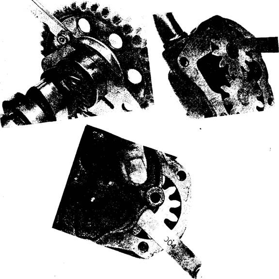
Fig. 20.28. Thickness gauges in typical measuring locations.
A square is used in check the squareness of parts. Parting surface flatness can be checked with a straightedge placed across a part in several directions. The amount of warpage or bend can be determined by trying to slide gauges of various thickness under the straightedge.
A dial gauge is a useful measuring tool, especially for determining differences or amounts of movement. The dial gauge face is divided into 0.025 mm divisions, and a full dial rotation indicates spindle travel of 2.5 mm. A dial gauge is specifically used to measure end-play and out-of-round and shaft run-out.
Supporting the object in V-blocks checks a bend in a cylindrical object or bearings at each end with a dial gauge tip placed against the centre. The dial gauge movement indicates bend as the object is turned. This type of bend measurement is called run-out.
Dial gauge on a special fixture are used to measure cylinders bore out-of-round and taper. A standard dial gauge with a support may be used to measure shaft end-play, gear backlash, valve-in-guide looseness, valve-opening travel, and flange run-out.
A vernier is another tool, which is used to measure either outside or inside dimensions within 0.025 mm. The jaws are placed across the item to be measured and the dimension is shown on the scale similar to the scale on the micrometer barrel. Vernier divisions are shown on the slide, one of which lines up with a division mark on the scale. This aligned vernier division is added to the scale value to determine the part size to the nearest 0.025 mm. A dial gauge and vernier are shown in Fig. 20.29.
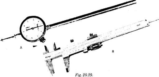
A. A dial gauge. B. A vernier calliper.
Hole sizes are determined accurately with a small ho le gauge or telescopic gauge used with an outside micrometer illustrated in Fig. 20.30. The largest gauge that fits in the opening is placed and expanded to the opening size. The gauge is then taken out from the opening and is measured with the micrometer to determine the opening size.
Clearances between closely fitting assembled parts, such as bearing clearances, can be accurately measured with Plastigage strips. A strip of Plastigage is laid across the area being measured. The parts are assembled correctly, tightened to the correct torque, and then disassembled. The width of the Plastigage crush indicates the amount of clearance (Fig. 20.31). The smaller the clearance, the more crush exists, making the Plastigage pattern wider.
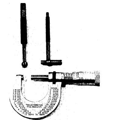
Fig, 20.30. Hole gauge or telescopic gauge.

Fig. 20.31. Typical use of Pastigage crushes to measure clearance.
Highly stressed parts used in performance engines are checked for cracks with specialized non-destructive testing procedures. A magnetic particle inspection called Magnaflux is used to check cracks in iron and steel parts. In this process, the part is magnetized and covered with ‘ iron particles. These particles are attracted to any magnetic pole that forms adjacent to a weak area or on cracks. A crack made visible by Magnaflux is pictured in Fig. 20.32.
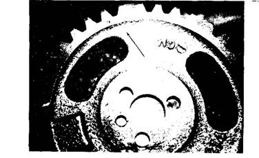
Fig. 20.32. Magnetic particle inspection showing a crack in a gear.
Parts made from nonmagnetic materials are checked with a fluorescent penetrant called Zyglo. The clean part is dipped in the penetrant, rinsed, and dipped into a developer. The part then is inspected under an ultraviolet light. The penetrant soaks into a surface crack, which is seen as a white line.
