33.15
Heater and Air-conditioner Service
33.15.1.
Manifold and Gauge set
Gauge set is a basic tool for taking up air-conditioning services. It is essential for measuring system pressures, which in turn indicates accurately system performance. Normally a two-gauge manifold set (Fig. 33.66) is sufficient for attending to most automotive air-conditioners. Some systems, however, require a three-gauge set or a single gauge in addition to a two-gauge set.

Fig. 33.65. Combined case Iduct system.
A. 100% recirculated air through the evaporator core to the dash panel air conditioning outlets.
B. 100% fresh air through the heater core and out through the floor outlets.
C. Position of the HI/LO door and the DEF/AC door, a portion of the heated air is diverted to the efroster outlet.
In a two-gauge set, one gauge is used on the low pressure (suction) side and the other on the high pressure (discharge) side of the system. Systems requiring the use of a third gauge have a second low pressure side fitting, which requires a low pressure gauge.
Manifold.
The gauges are connected into the air-conditioning system through manifold and high-pressure hoses. The manifold (Fig. 33.66) has the provision for the connection of gauges and hoses. Two hand wheel valves are provided on the manifold for controlling the flow of refrigerant through the manifold. The hose connection fittings on the low and high pressure side are respectively below their gauges, and the centre hose fitting of the manifold is used for charging, evacuation, or any other service required. Different positions of the hand wheel valves provide the following situations.
(i) When both valves are closed (by complete rotation in the clockwise direction), the manifold is closed and pressures can still be recorded on each gauge.

Fig. 33.66. Manifold and gauge set with hand wheel valves and hoses. (ii) When both valves are opened the system is connected to the centre hose port of the manifold set.
This situation arises when refrigerant is required to enter or leave the
system. The pressures indicated on the gauges are not accurate because of the mixing
of low and high pressure values, (iit) When only one valve is opened, the side with the open valve is connected to the central
port and refrigerant is allowed to flow through the valve. The gauges in this case
indicate the respective readings.
Low Pressure Gauge.
The low pressure gauge (Fig. 33.67A and B) is called a compound gauge, which gives both vacuum and pressure indications. For below atmospheric pressure, some manufacturers use
millimeters of mercury (mm Hg) and kilograms per square centimetre (kg/cm ) for above atmospheric pressure. Other sources use negative kilopascal (- kPa) values (3.38 kPa = 1 in Hg)
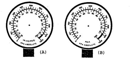
Fig. 33.67. Compound gauge.
A. Showing psi (gauge) and kPa (absolute). B. Showing absolute scale,
pressure scales for comparison.
for below atmospheric pressure, and positive kilopascal (+ kPa) values (6.895 kPa = 1 psig) for above atmospheric pressure.
High Pressure Gauge
The high pressure gauges (Fig. 33.68A and B) are scaled either in kg/cm or kPa (6.895 kPa = 1 psi = 0.070308 kg/cm2) and indicate values above atmospheric
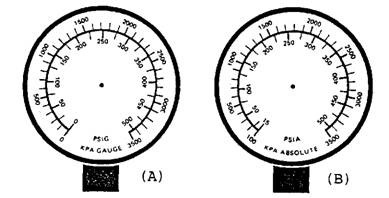
Fig. 33.68. High pressure gauge.
A. Showing psi (gauge) and kPa (gauge) pressure scales for comparison.
B. Showing psi (absolute) and kPa (absolute) pressure scales for comparison.
33.15.2.
Charging
Charging hose is designed to withstand working pressures above 3345 kPa and burst pressure rating of up to 13750 kPa. Blue colour hose is used on the low pressure side, red is used on the high pressure side, and white or yellow is used for the central port. The end of standard charging hose is compatible for the 6 mm flare fittings of the manifold set and compressor access ports.
33.15.3.
Leak Detection
There are several methods used for the detection of leaks in the refrigeration system, which can be as simple as using a soap solution and as complicated and expensive as electronic equipment. Halide gas touch is the most commonly used leak detection instrument.
In many instances, the leak in the air conditioning system may be either a cold leak or a pressure leak. A cold leak occurs when the unit is not at its operating temperature. A pressure leak occurs during the periods of high pressure within the system, such as when the automobile is slowly running in heavy traffic on a very warm day.
Halide Leak Detector.
Halide leak detector (Fig. 33.69) can detect a leak as slight as 0.4536 kg in ten years. This instrument is popular because of its low initial cost, ease of handling, and simplicity in construction and operation. It consists of two major parts; the detector unit and the gas cylinder. The gas cylinder is a non-refillable pressure tank containing a gas such as propane or butane. The detector unit consists of a valve (which controls the flow of gas to the burner), the burner (which is a chamber where the gas and air are mixed), and the search hose (a rubber tube through which air passes to the chamber).
After igniting the gas and air mixture, the flow of gas is regulated until the flame burns about 6 mm above the opening in the reactor plate. The plate is heated by the flame to a red-hot
temperature. When the search hose comes into contact with leaking refrigerant, the refrigerant is drawn into the search tube and is brought to the receiver plate, where different colour flames are produced in the burner. If the flame colour is blue, there is no leak, if yellow-green flame leak is small, and if bright-blue purple flame leak is large. In some cases if leakage is severe, the flame is put out.
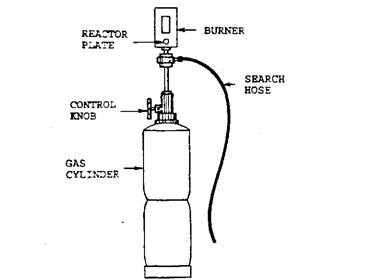
Fig. 33.69. Halide leak detector.
One should not breathe the fumes or black smoke that is given off when a leak has been located, as they contain poisonous phosgene gas. The flame type detector should not be used in an area where combustible vapour, fuel or dust is present, as there is possibility of explosion or a fire. The Halide leak detector requires relatively little maintenance. It may be necessary to replace occasionally the reactor plate, which is a part of the burner. Improper use of the detector may damage the search hose or block the burner with dust.
Soap Solution Leak Detection.
The soap solution is a more efficient method of locating small leaks, specifically in areas of limited access where a halide or electronic leak detector can not be used. Thick soap solution is applied using a paint brush to the area of a suspected leak and soap bubbles reveal the leak.
Leak Detection using a Dye.
To locate a cold leak or a pressure leak, sometimes a dye solution is introduced into the system. The colour of the dye is either red or yellow. After the automobile is driven a few days, the leak can be detected by dye trace. Once a dye is introduced into the system, it remains there until the complete system is cleaned out, the oil changed and the drier replaced. Also some are with the opinion that the dye can stick at the valves opening and can indicate only large leak.
Electronic Leak Detector.
Electronic leak detectors are the most sensitive of all leak detection devices. It can detect a rate of loss of R-12 as slow as 14.1 gm per year, which corresponds 100 ppm i.e. 100 parts of refrigerant to one million parts of air. This is an expensive and sophisticated device requiring more maintenance than the halide leak detector. Electronic leak detectors are also known as halogen leak detectors. The detector is portable, cordless and operated by a rechargeable battery.
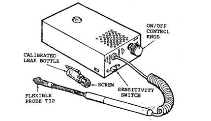
Fig. 33.70. Electronic leak detector.
To use the electronic leak detector (Fig. 33.70), the sensitive switch is placed in the search position and the control knob is turned clockwise until a steady ticking sound is heard. The probe tip is slowly moved over and under the places suspected of leaking and the ticking sound increases when the probe tip passes over a leak. For small leaks, the sensitivity switch is turned to pinpoint position, and the control knob is again readjusted for the steady ticking sound.
33.15.4.
Moisture and Moisture Removal
Moisture.
Refrigerant is considered to be moisture free, but it absorbs readily whenever exposed to moisture. Moisture normally enters from outside sources during replacement of oil or refrigerant. Whenever a unit is removed from the system for repair or replacement, air is introduced into the system, due to which there is possibility of entering of moisture. Any moisture introduced into the system in excess of the amount that the desiccant can absorb in the receiver-drier, is free in the system. The moisture content of new refrigerant should not exceed 10 ppm. Moisture in concentration greater than 20 ppm causes serious damage. A drop of water in the air-conditioning system corresponds to approximately a 40 ppm concentration.
R-12 reacts chemically with water to form hydrochloric acid, which is highly corrosive to all the materials in the system, and the formation process speeds up with heat generated in the system. The corrosive process creates oxides, which form a sludge with the refrigerant and plug the screens in the thermostatic expansion valve, compressor inlet, and the drier itself. If the moisture is allowed to remain in the system for a long time, pinholes due to corrosion appear in the evaporator and condenser coils, and system tubing. In addition aluminium parts of the compressor corrode making it unserviceable. A similar situation may occur in the valves and fittings.
Moisture Removal.
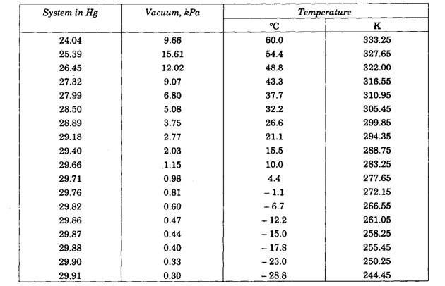
Whenever there is evidence of moisture in a system, a thorough cleaning of the system is recommended followed by the installation of a new drier. A vacuum pump is a must for air conditioning service. Moisture is removed from the air-conditioning system by creating a vacuum. In the vacuum condition moisture evaporates due to decrease in boiling point (Table 33.2). The vacuum pump then removes moisture in the form of vapour from the system. A good vacuum pump is capable of evacuating a system to a pressure of 0.81 kPa absolute (29.76 in Hg) or better. At this pressure water boils at 277.69 K (4.44°C). The amount of moisture removed depends on the degree of vacuum achieved and time the system is subjected to a vacuum. The recommended minimum pumping time is 30 minutes; however, a four-hour pump-down achieves better result.
The above description holds true for normal atmospheric pressures prevailing at sea level (101.3 kPa absolute) and also for higher pressure at higher altitudes if the boiling point is reduced to a point below the ambient temperature. However the efficiency of vacuum pump is reduced at high altitudes. For example a vacuum pump capable of pumping 0.27 kPa absolute (29.92 in Hg) at sea level can only pump 15.44 kPa absolute (25.44 in Hg) at 1609 m above sea level. To compensate for this problem, the ambient temperature must be raised above 327.7 K (54.44°C), under the hood, which is achieved by running the engine with th, air conditioner turned off.
Table 33.2. Boiling point of water under a vacuum.
Heating System Problems and Service
The common problems associated with heating systems are as follows.
Little or no Heat. This problem may be due to (i) inefficient air circulation, («) blockage of coolant hose, (Hi) presence of air in heater core, (iv) clogging of heater core, (u) malfunctioning of heater water valve, (v i) low coolant level in engine cooling system and /or, (vii) malfunctioning of engine cooling system thermostat.
All the above causes are to be checked one by one and the faulty ones are to be repaired or replaced accordingly. If the hose is defective it requires replacement. If the problem is associated with core, it has to be repaired or replaced. Air is to be bled out if found in the core. Coolant is to be added to makeup the level if down. If the water valve is defective, it requires repair or replacement. A faulty thermostat requires replacement.
Too much Heat.
This happens if temperature door is out of adjustment (which requires readjustment), or if the engine cooling system thermostat is stuck closed (requiring replacement).
Insufficient Defrosting.
This problem takes place if (i) defrost door control cable is out of adjustment, requiring readjustment, (ii) defrost outlet is blocked, requiring cleaning, or (u) any cause of little or no heat which requires attention.
Blower Motor Inoperative.
This is due to a blown fuse, poor electrical connections, a defective motor, or the resistor being open. Accordingly the fault has to be identified and attended.
Coolant Leakage.
One has to check hoses, hose connections, heater core and water valve, and attend accordingly.
Vent Door does not operate.
This could happen due to a defective vacuum motor, leaky vacuum connection, or a defective control assembly.
Controls Hard to operate.
This could happen due to a loose or binding control cable, or a sticky door.
Odour from Heater.
This happens if air leaks around blower case or coolant leaks around heater core.
• 33.15.6.
Air Conditioner Service
There are number of preliminary checks that must be made when checking the refrigeration system.
(a) The drive belt must have proper tension and be in good condition. (6) The air conditioning clutch must be functioning properly.
(c) The thermal fuse must be in order.
(d) All air-conditioning components should be mounted securely.
(e) The condenser, which is mounted ahead of the radiator, should be externally clean.
(/) The air conditioner hoses and lines must be in good condition and properly supported.
(g) There should be no trace of oil leaks on the hoses or connections.
(h) The temperature of air coming from the cooling duct, when the air-conditioner is set at the full cold mode and the engine is operating at fast idle, should be within 275 to 277 K with high air flow.
Performance Testing and Problem Diagnosis.
The gauge is to be connected to the system through the manifold. The gauge set valves are closed and the hoses of the gauge set are then connected to the system service valve fittings. The high pressure hose is connected to the condenser side and the low pressure hose is connected to the evaporator side. The service valves on the compressor can then be opened. Air must be removed from the gauge set and hoses. The process of removing air is called purging. First open the low pressure valve slightly until refrigerant begins to come out of the centre hose; then close the valve. Similarly just crack the high pressure valve until refrigerant comes out and then close it. The purging is over. Valves should not be opened too much. The refrigeration oil used for compressor lubrication also comes out with the refrigerant.
With the gauge set in place, the refrigeration system performance can be checked. Generally the performance is checked when the air conditioner is set on full cold with the automobile windows open to provide a high heat load and the engine running at fast idle to operate the compressor. The engine is run for fifteen minutes to stabilize the system. The outlet duct air temperature and the compressor inlet and outlet pressures are read, and also the wet bulb temperature. These readings are compared to the specifications that apply to specific automobile being tested.
Excessive high pressure is the result of an overheated condenser, restricted refrigerant flow, flooded evaporator, or too much refrigerant in the system. When the refrigerant charge quantity is too low, the high pressure gauge indicates low pressure. If both gauges show nearly the same pressure the compressor is not pumping properly. A faulty suction throttling valve or starved evaporator gives very low inlet pressures. The inlet pressure must stay above 152 kPa to keep the evaporator temperature above the freezing point of moisture.
One of the most common causes of inadequate cooling is the loss of refrigerant. During normal operation the refrigerant gradually seeps through the hoses and fittings so that the refrigerant has to be replenished after every three or four years of normal service. More rapid loss results from leakage. The leakage should be located and repaired and then the system has to be recharged with refrigerant.
The sight glass incorporated with the receiver-drier is helpful in diagnosing the problem. If sight glass gives a milky appearance, then water is present in the system. Occasional or slow moving bubbles on the glass means refrigerant is slightly low or receiver-drier is saturated and releasing moisture. If foam or continuous flow of bubbles is seen on the glass then refrigerant is very low. When quantity of refrigerant is low some of the refrigerant vaporizes and form bubbles in the flow which can be seen as they flow past the sight glass. Bubbling can also occur if the suction throttling valve is not functioning or if there is a restriction between the sight glass and condenser. If oil streaks on glass are seen then there is a complete absence of refrigerant. If glass is clear then normal operation of a charged system or that the system is empty.
Before the system is recharged it should be checked for leaks using the procedures explained in section 33.15.3. The refrigeration system is discharged and recharged through a gauge set.
Discharging.
When leaks or faulty components are found in the refrigeration system, the system must be discharged before the repair work is accomplished. With the gauge set in place, the high pressure valve is opened slightly to allow the refrigerant to escape through the centre hose of the gauge set. The open end of the hose should be placed on the floor close to a shop exhaust vent. The refrigerant is allowed to escape slowly so that no oil is lost. When the system becomes empty, necessary repair can be made. Whenever the system is opened the opening should be immediately plugged to minimize the chance of getting moisture or dirt into the system. Refrigerant oil should be added to maintain the required level. It is always preferred to drain the use oil and replace it with fresh oil.
Evacuating.
The evacuation process removes all of the air and moisture from the system. The refrigeration system is evacuated with a vacuum pump. At the low pressures that prevail in a vacuum condition, any moisture that is in the refrigeration system evaporates. It is pumped out of the system by the vacuum pump. The centre of the gauge set is attached to the vacuum pump, keeping both the valves closed. With the vacuum pump operating, service valves and both gauge valves are opened slowly so that no refrigerant oil is forced out of the system. If the system is leak free it pumps to 660 to 711 mm of vacuum, depending on the atmospheric pressure and altitude at which the work is done. The vacuum pump should be run for thirty minutes at maximum vacuum condition to remove the maximum amount of moisture. With the vacuum pump still operating, both the gauge and the service valves are closed, and the vacuum pump is then turned off. Vacuum should hold for ten minutes if there is no leak in the system. If leak exists, about 0.5 kg of refrigerant should be put in the system and the leak detector is used to locate the leak.
Charging.
After the system is evacuated, the centre hose of the gauge set is removed from vacuum pump and connected to the refrigerant supply tank. The supply is turned on and the centre hose loosened at the gauge set to purge air from the hose. Each valve is opened for a few seconds as the hose is loosened on the supply tank to purge the air from the hoses.
The high pressure valve is fully opened to allow refrigerant to flow into the evacuated refrigerant system. The amount of refrigerant that is required is measured by refrigerant weight. If the refrigerant is taken from the bottom of the supply tank, the supply tank can be inverted. If liquid filling does not fully charge the system the supply tank should be heated to 328 K, using a water bath for small supply cans. When the correct amount of refrigerant is in the system, the gauge and service valves are closed. The system should be rechecked for leaks before the gauge set is removed. If there are no leaks, the gauge set can be removed. A cloth should be placed around the high pressure gauge fitting before loosening it to prevent injury if some of the high-pressure refrigerant escapes. Refrigerant evaporates very rapidly. As it evaporates it absorbs heat. If the expanding refrigerant falls on one’s body it freezes the skin immediately.
