29.6.
Gas Discharge Lamps and Single Light Sources
29.6.1.
Gas Discharge Lamps
Only through recent developments the gas discharge headlamps (GDL) have found use in vehicles. They provide more effective illumination and have the potential for new design possibilities for the front of a vehicle suiting to the aerodynamic styling with appropriate lighting positions from the considerations of economy and safety. The GDL system consists of three main components, such as lamp, ballast system and headlamp.
Lamp (DD.
The operation of this lamp is different from the conventional incandescent bulbs and requires a much higher voltage. Figure 29.29 illustrates the operating principle for a gas discharge (GD) bulb.
Ballast System.
The ballast system uses an ignition and control unit. This unit converts the electrical system voltage into the voltage for the operation of the lamp. This controls the ignition stage, run up, and regulation during continuous use. It also monitors operation from a safety point of view.
Headlamp.
The headlamp is more or less similar to conventional units. However, to meet the limits set for dazzle, a more accurate finish is necessary which increases production costs.
An electric arc is the source of light in the gas discharge lamp, and the actual discharge bulb is only about 10 mm across. Two quartz glass electrodes protrude into the bulb. The gap between these electrodes is 4 mm, and the distance between the end of the electrode and the bulb contact surface is 25 mm, which is the same as in the standard HI bulb.

Fig. 29.29. Operating principle of a GD bulb.
At room temperature and under pressure the bulb contains a mixture of mercury, various metal salts and xenon. The xenon illuminates immediately after the light is switched on and evaporates the mercury and metal salts. The metal vapour mixture produces the high luminous efficiency. Most of the light is generated by the mercury and the colour spectrum is provided by the metal salts. Figure 29.30 compares the spectrum of light produced by the GDL bulb and a halogen HI bulb. The following table represents the output from the DI and HI bulbs and the figures are approximate for comparison only.
| Bulb | Light | Heat | UV radiation |
| HI | 8% | 92% | < 1% |
| DI | 28% | 58% | 14% |

Fig. 29.30. Comparison of spectrum of light produced by the GDL (left) and a halogen HI bulb (right).
From safety view points the high output of UV radiation from the GDL system requires special filters. The luminance of the GDL and an HI bulb is compared in Fig. 27.31. The average output of GDL system is three times that of an HI bulb.
For starting of the DI lamp it has to run through in sequence the following four stages.
Ignition.
A high voltage pulse causes a spark to jump across the electrodes, which ionizes the gap and creates a tubular discharge push.
Immediate light.
The current flowing along the discharge path excites the xenon, which consequently emits light at about 20% of its continuous value.
Run-up.
The lamp is now operated at increased wattage, and the temperature rises rapidly due to which the mercury and metal salts evaporate. The pressure in the lamp also increases with the increase of luminous flux. Consequently the light shifts from the blue to the white range.
Continuous.
The lamp is now operated at a stabilized power rating of 35 W providing a steady arc without any flickering. The luminous flux of 28000 lm and the colour temperature of 4500 K are reached.
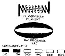
Fig. 27.31. Comparison of luminance of the GDL and a halogen HI bulb.
A ballast system (Fig. 29.32) controls the above stages of operation. A high voltage, in the order of 20 kV, is produced to initiate the arc. During run-up the ballast system limits the current and then the voltage. This wattage control permits the light to build up very quickly but prevents overshoot, which can reduce the life of the bulb. The ballast unit also takes care of radio suppression and safety aspects for which appropriate circuits are included.
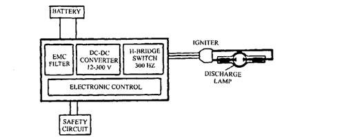
Fig. 29.32. Ballast system to control a GDL.
The headlamp system can be designed to suit the DI bulb, which produces 2.5 times the light flux at less than half the temperature of the conventional HI bulb. This permits for greater flexibility for the head lamp and styling. When the GDL system is used as a dip beam the self levelling lights are required due to the high luminous intensities. Use as a main beam may be a problem because of the on/off nature. For dip beam, which stays on all the time and is supplemented by a conventional main beam (four headlamp system) could be the most appropriate use.
29.6.2.
Ultra Violet Headlights
A great amount of work has been done by Hella on improving headlight quality and design. One major step is the development of gas discharge light (GDL), as discussed in the previous section. Hella has also been involved in utilizing the GDL for ultra-violet lights. The UV radiation is almost invisible but glow in the dark. It does not dazzle on coming traffic but illuminates fluorescent objects such as specially treated road markings and clothing. The UV light also penetrates fog and mist, and even passes through a few centimeters of snow.
Hella has also worked with Volvo and Saab in Sweden. In an experimental setup 80 km of roads have been prepared with fluorescent signs and markings. Four headlamp cars were used, with two conventional halogen dip lights and two UV lights. The UV lights come on at the same time as the dipped beams effectively doubling their range, but without dazzling.
Two stage blue filters are used to eliminate visible light. Precise control of the filter colour is used to filter out UVB and UVC, as these can cause eye damage and skin cancer. The remaining UVA is just beyond the visble spectrum and is used in sun-tan lamps for example. For further safety against close range vision into the faint blue glow of the lights, these lights are operated only when the vehicle is moving. Development work is still continuing, but this looks like a very promising contender to road safety.
20.6.3.
Single Light Source Lighting
Developments pertaining to the use of the gas discharge lamps for vehicle lighting system as described above have also provided a new way of using a central light source for vehicle
lighting. This new system could permit a reduction in headlamp size for the same output or improved lighting with the same size, however a trade off is likely to occur. Figure 29.33 demonstrates the use of a GDL system as central light source for all the vehicle lights.
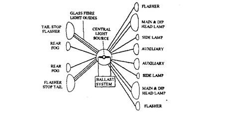
Fig. 29.33. Using a GDL as central light source for all the vehicle lights.
The light from the super light source is distributed to the headlamps and other lamps by a light guide or fibre optic link. The light from the GDL enters the fibre optics through special lenses and leaves the light guide in a similar manner (Fig. 29.34). A special lens distributes the required light. Functions such as indicators can be met through shields or even by electro-chromatic switches if they become available.
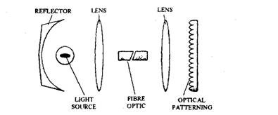
Fig. 29.34. Light from the GDL enters the fibre optics via special lenses and leaves the light guide in a similar manner.
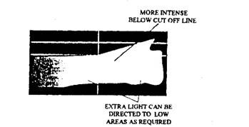
Fig. 29.35. As a head-light, the light from the GDL enters several glass fibre bundles.
A problem with this system may be heat build up in the fibre optics, which can however be alleviated to a large extent by using an infra red permeable coating on the reflector. Although the light guide system has a very low photometric efficiency (1 – 20% at best), the very efficient light source still makes this technique acceptable. The ability to improve the light distribution of the main headlamp is one of the main advantages. Several glass fibre bundles could be used with this new system to direct the light in an even distribution on to the desired areas of the road (Fig. 29.35). It is possible to place the central light source anywhere in the vehicle. Only one source is sufficient but a second can be used for safety reasons.
