14.7.
Dynamos
Dynamos operate on the same principle as the alternator but, with the basic difference that in the case of the alternator the magnetic field rotates with the conductor stationary, whereas in case of dynamo the magnetic field is stationary and the conductors are made to rotate.
A dynamo, in its simplest form (Fig. 14.9), consists of a horseshoe magnet with two poles formed at its open end. Between these poles a single conductor loop is mounted on a support spindle and the ends of the loop are joined to the two half split-ring segments. Two carbon brushes are placed on either side of the ring segments. The brushes transfer the generated and rectified direct current from the split segments to the external circuit for supply of electricity.
Fig. 14.9. Basic single-loop dynamo.
14.7.1.
Current Generation
Figure 14.9A illustrates how the rotating conductor loop is under the influence of the magnetic flux established by the magnet poles. An emf is induced into the conductors as the two
half-conductors cut through this flux so that a flow of current is produced. The direction of current flow is towards the rear of the loop in the black half-conductor adjacent to the North Pole, and is towards the front in the white half-conductor next to the South Pole. Flow of current, therefore, is in a clockwise direction through the loop, coming out at the right hand split-ring and brush and returning by the left hand brush and ring segment.
With a further half revolution of the conducting loop (Fig. 14.9B) the black half-conductor is placed next to the South Pole while the white half-conductor is placed adjacent to the North Pole. This reverses the direction of the current flow in each half-conductor.
14.7.2.
Commutation
As the both half-conductors are rotated, the reversal of current flow in them cannot be avoided, but the resultant flow of current can be made unidirectional using a special switch called commutator. This switch commutes or changes the current flow from an alternating current into an unidirectional one by reversing the connections between the armature loops and the external circuit in sequence with the reversals of current in these loops.
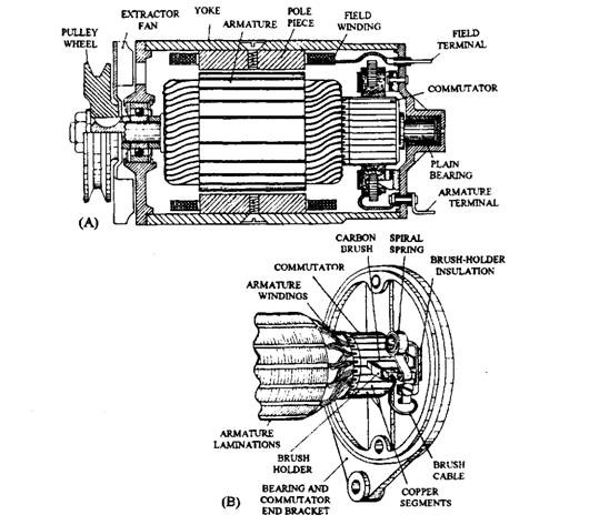
Fig. 14.10. Dynamo. A. Section view. B. Detail of commutator and brush-gear.
For commutation the two ends of the conductor loop are connected to two half split-ring segments, which make rubbing contact with a pair of conducting carbon brushes placed on either side (Fig. 14.9A and B). As the conductor loop and the split-ring segments rotate together, the two half-conductors continuously pass through the magnetic fields of the north and south poles. During this rotation each half segment moves from one brush to another. When the direction of the current flow is changed in the conductors, the segments switch over and make contact with the opposite brush so that the direction of the current flowing to and from each individual brush remains the same. The split-ring and brushes, therefore, act as a mechanical switch to rectify the alternating current so that only a direct current is passed on to the brushes and hence to the external circuit.
The direct current generated in a single-loop armature fluctuates from zero to a maximum and then back to zero for every 180 degrees of rotation. Therefore prototype armatures contain a number of evenly spaced loops and split-ring segments so that when the voltage declines in one or more loops it increases in others. All the individual currents are continuously collected by the brushes as they contact each pair of commutator segments so that a combined steady direct-current output (Fig. 14.10B) is produced.
14.7.3. Output Control and Regulation
The simple dynamo in Fig. 14.9 has no control over the amount of voltage and current generated when the armature speed increases. But the voltage and current output (Fig. 14.10A) from a dynamo in use is controlled by varying the strength of the magnetic field established between the poles. This is achieved by converting the permanent-magnet poles to electromagnets by winding coils (known as the field windings) around each soft-iron pole-piece (Fig. 14.10B).
Regulation of the generator output is carried out by limiting the field windings current and so, reducing the magnetic field strength. A pair of vibrating contacts is put in series with the field winding circuits. The contacts open when the generator output reaches the upper limit and close with increasing frequency as the generator speed rises or the battery demands are high. A resistor is shunted across the points to prevent excessive contacts arching during opening. When contacts open, a reduced flow of current passes through the resistor in preference to jump the contacts.
14.7.4. Cut-out
The cut-out is a type of switch, which disconnects the battery from the generator and reconnects it when the generated voltage exceeds the • battery voltage. In absence of this switch if the generator and battery are permanently connected together, the battery would discharge through the generator armature to earth when the generator is either stationary or when its generated output voltage is less than that of the battery.
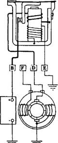
The cut-out consists of a pair of contracts operated by an electromagnet relay, which senses any change of generated voltage and automatically breaks or joins up the battery to the generator circuit. The electromagnet relay has two bobbin windings, one connected in shunt (parallel) with the generator output and the other in series with the battery and the generator (Fig. 14.11). The series winding circuit is opened by
Fig. 14.11. Cut-out.
the contact, and are held open by spring tension. When the generator output voltage rises above that of the battery due to increase in its speed, the magnetism of the shunt winding overcomes spring tension and closes the contacts. Charging current now flows from the generator to the battery through the series winding. The extra magnetism is now created to assist that of the shunt winding to hold the contacts together.
When the generator output voltage becomes less than the battery voltage due to fall in its speed, current begins to flow in the reverse direction, i.e. from the battery to the generator through the series winding. The magnetism of the series winding now opposes and partially cancels the magnetic field of the shunt winding, so that contacts open under spring tension, thereby disconnecting the generator from the battery.
14.7.5.
Current Control
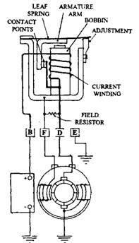
Output current from the generator is controlled to safeguard its windings against overloading due to excessive current demands of the utilities such as a flat battery or perhaps a large lighting or heater load. Control is achieved through a series current winding wound on to a relay bobbin (Fig. 14.21), so that the current flowing through the generator field windings is interrupted when the set maximum charging rate has been reached.
At the increased speed, current from the generator (dynamo) flows to the battery through the series current winding. When the generated current attains its maximum, the series bobbin winding is sufficiently energized to pull the L-shaped armature arm downwards so that the contacts open against the tension of the leaf spring. The generator field winding circuit then opens, as a result of which the magnetic field strength across the generator poles reduces and the output falls. Consequently the energizing current in the series bobbin winding falls so that the regulator contacts close again to allow the output to rise. This opening and closing cycle repeats at between 60 and 100 times per second and thereby limits the maximum output current flow.
14.7.6.
Voltage Control
In addition to current control, the maximum generated voltage is also controlled, which otherwise continues to increase with rising speed. This voltage build-up blows components like light-bulbs, heater elements, and other electrical equipment.
The terminal voltage of the battery rises, as it becomes charged causing a general increase in line voltage between the generator and the battery. When the line voltage reaches its set value, the voltage shunt winding wound on to a relay bobbin is sufficiently energised to pull downwards the armature arm (Fig. 14.13), so that the contacts open against the spring tension. Now the field resistor is in series with the generator field winding so that the field exciting current is reduced and
Fig. 14.12. Current regulator.
Fig. 14.13. Voltage regulator.
so also the generator’s magnetic field strength causing a drop in the generator output voltage. In practice the cut-out, and the current and voltage regulators are built as one control unit.


