22.9.
Design of Chassis Springs
22.9.1.
Laminated or Leaf Springs
The semi-elliptic type of leaf spring has a main leaf, rolled each end to form an eye and a number of leaves, having gradually decreased lengths are clamped to it. This type of spring may be considered equivalent to two cantilever beams, loaded at the ends, so that the upper and the lower surface of the leaf are at the maximum tension and maximum compression respectively. Practically the failure of leaf spring occurs due to fatigue that always starts on the tension side of the spring leaves because of tensile strength of the material being less than its compressive strength. The stress varies linearly from maximum at the surface to zero at the central axis (called neutral axis) thereby giving an average stress exactly one-half that of the maximum.
For the purpose of analysis, first consider the simplest form of leaf spring that consists of a single leaf shown in Fig. 22.44.
Let, I = length of the spring, m
w = width of the spring, m
t = thickness of the spring, m
P = load on each end of the spring, N
E = Modules of elasticity, Pa
/ = Moment of inertia of the section

Fig. 22.44. A simple single leaf spring.

where R = the radius of curvature of the spring, m
Z =the perpendicular distance between the line joining the centres of the eyes of a half-elliptic spring and the inner side of the main leaf, m
I = the length of the main leaf, m.
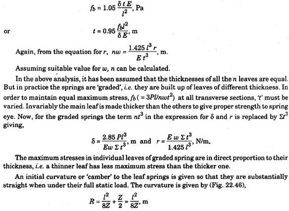
However, if in a graded spring all the leaves are curved to same radius, then evidently the stresses in the springs are different. To overcome this problem, ‘nipping* is done, i.e. the thinner leaf is curved to a smaller radius than the thicker one. Therefore, while calculating the stress in any leaf due to given deflection, the initial position or negative stress due to nipping must be taken into account. The stress adds to the initial positive stress and over comes the initial negative stress.
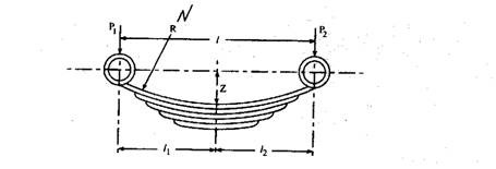
Fig. 22.46. Semi-elliptical springs are supported off centre.

where, 81 and 82 are the deflections under load Pi and Pi respectively.
The leaves have their ends tapered in order to have same rate of change of resisting moment to ensure uniform stress distribution over the whole length. This cannot be achieved if the ends are cut off square, because the bending moment increases uniformly from the end to the middle of the spring while resisting moment changes in steps at the end of each leaf.
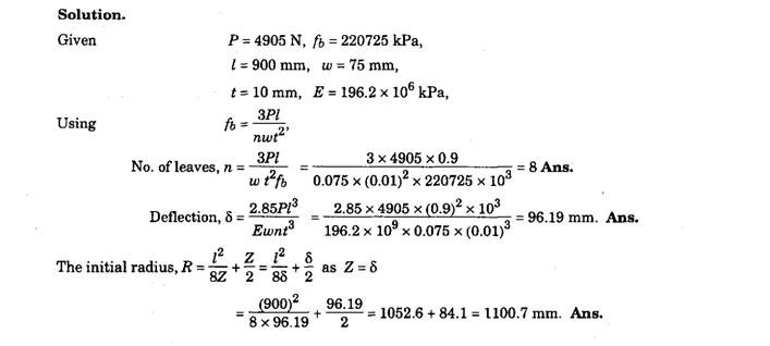
Example 22.1. A vehicle spring of semi-elliptic type has leaves of 75 mm width and 10 mm thickness and effective length 900 mm. If the stress is not to exceed 220725 kPa when the spring is loaded to 4905 N, estimate the required number of leaves and the deflection under this
condition. If the spring is just flat under load, what is the initial radius ? Take E = 196.2 x 10 kPa.
22.9.2.
Coil Springs
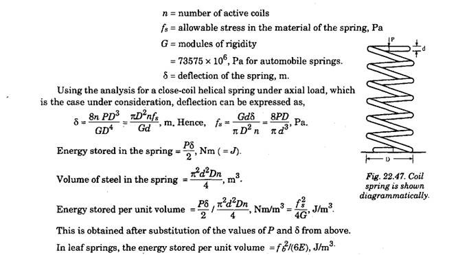
Coil springs are mainly subjected to torsion. The failure of the spring occurs due to shear. The stress varies uniformly form a maximum at the surface to zero at centre of the circular cross-section. The average stress is equal to two-thirds the maximum. A coil spring is diagram-matically shown in Fig. 22.47. At both the ends of the coil spring, there is a dead coil, smaller in size to the main spring and ground off flat so that it can rest on the spring seat properly.
Let, P = axial load on the spring, N
d = diameter of the spring, m
D = mean coil diameter, m
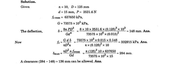
Example 22.2. A typical coil suspension spring has 10 effective coils of a mean diameter 125 mm and made out of wires of diameter 15 mm. The spring is designed to carry a maximum static load of3531.6N. Calculate the shear stress and the deflection under the above loading.
If a maximum shear stress of 637650 kPa is allowable in the material, then what is the
possible clearance in the spring ? Take the value ofG = 73575 x 10 kPa.
22.9.3.
Torsion-bar Springs
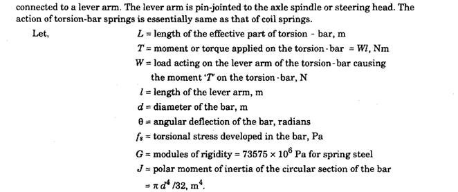
A rod or tube acting in torsion can work as a torsion-bar spring. The torsion-bar is a bar of spring steel that is anchored to the frame at one end while the other end is freely supported and
Torsion-bar should be designed under maximum dynamic load (bump load) considerations and the corresponding allowable stress. For a passenger car, the maximum bump load is about 165 percent of the maximum static load. But in practice, it is assumed to be 200 percent of the maximum static load based on the fact that the load rate in case of torsion-bar increases quite rapidly with the approach of the point of maximum deflection. The maximum allowable stress in torsion bar springs varies from 73575 to 93195 Pa with pre-stressing.
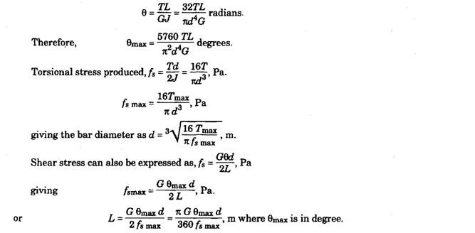
Deflection of the bar under torsional moment is given by,
If the arm of the torsion-bar is inclined upward considerably instead of making it horizontal, increase in deflection with increase in load is smaller. When the arm is horizontal, the movement of the chassis is equal to the movement of the free end of the arm around its pivot. Figure 22.48
illustrates diagrammatically a torsion-bar arm extending upward. Line OY represents the position of the arm in the unloaded state; OX represents its position under maximum bump load and OZ represents its position under maximum static load.
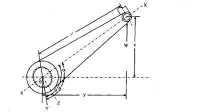
Fig. 22.48. A torsion-bar arm extending upward is shown diagrammatically.
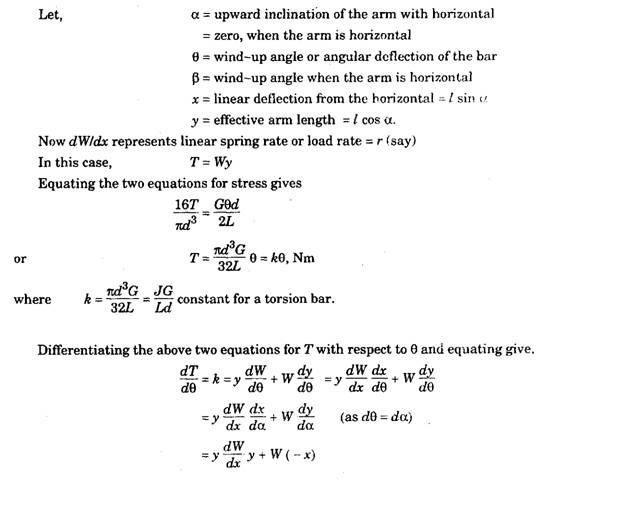

For non-circular section the value of k is different and it can be determined. The values of r and x are positive when arm is inclined upward and negative when inclined downward from the horizontal. For r to be minimum (this is required because of design considerations viz., it gives approximately the rate of normal static load) drldx = 0, but it does not give a simple expression that can be used.

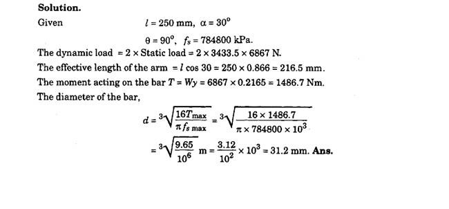
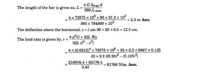
Example 22.3. A torsion-bar suspension is to be designed to support a maximum static load of3433.5 Nat the end of a lever arm 250 mm long. The deflection of the lever above the horizontal is to be 30° with a total angle of deflection of 90°. Assuming a safe allowable stress of 784800 kPa, calculate (a) the diameter of the torsion bar, (b) the effective length and (c) the load rate.
