34.3.
Description of Electric Vehicle
The major assemblies of a basic electric vehicle are
(a) body,
(b) chassis,
(c) drive motor,
(d) propulsion battery,
(e) controller, and
(/) auxiliaries and instrumentation. The electric vehicle has a DC series motor with shunt limiting winding in place of the IC engine. The rest of the transmission system is as in the conventional internal combustion vehicle. The speed of the motor is varied by varying the voltage across the motor smoothly and steplessly through the accelerator controlled reference signal. The vehicle incorporates a fuse to protect the system in case of a fault, a current limiter to limit the current to present values, a thermistor to sense the motor winding temperature and to trip the system if the winding temperature exceeds the preset safe value. Micro processors are being used in some of the speed controllers for optimal efficiency control of the drive system, for logic and sequencing, for indicating state of charge, self diagnostics etc. The advances in semiconductor device technology, particularly the availability of high power transistors and high power gate turn off thyristors make the use of the AC drives in battery vehicles a realistic possibility.
Range per charge is the maximum distance that the electric vehicle can cover before recharging the batteries or giving a boost charge. The maximum range per charge attained till recent time is 300 km (using zinc-air battery) with a top speed of 100 kmph. The electric vehicle can be designed for higher acceleration and for higher grade climbing ability for any specific requirement but at increased cost. In cold and poor weather conditions the range of some electric vehicle may be significantly reduced.
Considerable work is in progress in many parts of the world on the development of high energy density batteries for electric vehicles to increase their range per charge. Some of the near term high density batteries for electric vehicle are improved lead-acid, nickel-metal-hydride, zinc-air, lithium-ion etc.
Figure 34.3 provides the comparison of energy flow between the internal combustion and the battery vehicle. The comparison on the basis of their characteristics is presented in Table 34.1.

Fig. 34.3. Comparison of energy flow between EV and IC engine vehicle.
A number of factors are considered while designing the electric vehicle, but the most important among them are
(i) the type of batteries, and
(it) the type of drive system.
The great advantage of lead acid batteries is the existing mature technology, which is commonly used in the vehicle industry. The disadvantage is the relatively low specific power. Although the sodium sulphur battery seems to be the best contender but at present it is very costly and requires further developments to cope with the operating conditions such as the high temperature. Table 34.2 summarizes the choice of batteries.
Table 34.1. Comparison of characteristics between EV and IC engine vehicles.
| Item | Battery vehicle | IC engine vehicle |
| Investment cost | 1.5 to 1.8 times | 1.0 time |
| Running cost | 0.2 to 0.4 times | 1.0 time ; |
| Maintenance cost | Negligible | High |
| Power plant utilization | Increased | Nil |
| Life | High | Low |
| Resale valve | High | Low |
| Atmospheric pollution | Nil | Very high |
| Noise pollution | Nil | Very high |
| Foreign exchange expenditure | Negligible | High |
There are several choices of the type of drive. The basic, however, is choice either an AC or DC motor. The AC motor provides many control advantages but requires the DC produced by the batteries to be converted using an inverter. The DC shunt wound motor, rated at about 45 kW, appears to be one of the popular choices for the smaller electrical vehicles.
34.3.1.
Layout of a Typical System
The actual layout and interconnection of components on an electric vehicle depends on the type of batteries and drive motor used. Figure 34.4 illustrates a typical layout of a system that uses sodium sulphur batteries and a shunt wound DC motor with conventional brushes. The figure in the form of block diagram shows the full electrical system.

Fig. 34.4. Layout of a system using sodium sulphur batteries and a shunt wound DC motor.
By altering the field current and/or the armature current, the speed and torque of this type of motor are varied. Figure 34.5 shows control characteristics normally used on this type of drive system. The vehicle accelerates from starting. During initial stages of acceleration, the field current is held constant and the armature current is maintained to match the demand. As speed increases the field current is decreased, which weakens the main fields, thereby reduces the back emf from the armature. The armature current demand can be met, by increasing the speed. Normally this type of motor is air cooled although some systems use liquid coolant. The system efficiency is maximized through a variable regenerative braking system, which recharges the batteries during braking.
Table 34.2. Choice of some batteries for electric vehicles.
| Battery | Specific power, W/kg | Operating temperature, °C | Cycle life |
| Lead acid | 80-100 | ambient | 500-1000 |
| Sodium sulphur | 100-200 | 300-350 | > 1000 |
| Sodium nickel chloride | 100-200 | 290-330 | > 1000 |
| Lithium aluminium iron disulphide | 400-450 | 400-450 | >750 |
| Lithium solid polymer electrolyte | 250-400 | 120 | 300 |

Fig. 34.5. Control characteristics used on this type of drive system.
Batteries are connected in series to increase the voltage as motor design becomes easier for operation at higher voltages, since less current is required for the same power transfer. A battery management system controls the battery charge and discharge rates to the optimum value. A number of warning signals are built-in to indicate any abnormal conditions. The remaining range of the vehicle is also displayed on the instrument pack in the normal way.
The drive controller uses power transistor technology where the transistors are controlled by a microprocessor and their characteristics are set by software. Simple potentiometers are used to provide input signals from the brake and accelerator pedals to the controller. Signals from the other controls are provided by basic switches. The rest of the vehicle electrical system is normally controlled by installing a conventionall2 V lead acid battery, which is charged from the drive batteries using a DC/DC converter.
34.3.2.
Drive Motors
The drive motors can be of either AC or DC types. It is, however, difficult to distinguish between an AC motor and a brushless DC motor. Several types of motors either in use or serious contenders are presented as follows.
AC Motors.
All AC motors normally work on the same principle where a three phase winding is distributed around a laminated stater that sets up a rotating magnetic field. The speed of this rotating field can be calculated using the equation,
n = 60 f/p
where, n = speed in rpm
/= frequency of the supply
and p = number of pole pairs.
Asynchronous Motor.
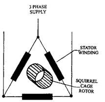
The asynchronous motor often uses a squirrel cage rotor consisting of a number of pole pairs. The stator is usually three phase and of either star or delta wound (Fig. 34.6). The rotating magnetic field in stator induces an emf in the rotor that causes current to flow because of a complete circuit. This produces magnetism, which reacts with the stator original field causing the rotor to rotate. The amount of slip (difference in rotor and field speed) is about 5% when the motor is most efficient.
Synchronous with Permanent Excitation.
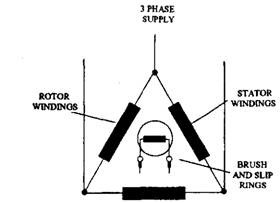
The synchronous motor (Fig. 34.7) uses wound rotor known as the inductor. The windings are magnetised by a DC supply through two

Fig. 34.6. Representation of the asynchronous motor.
slip rings. The magnetism locks on to the rotating magnetic field and produces a constant torque. If the speed is less than ‘n’ (= 60 f/p presented above) the torque fluctuates allowing high current to flow. The motor incorporates a special arrangement for initiating rotation. It makes an ideal generator, which is similar to the normal vehicle alternator.
Electronically Controlled (EC) Motor.
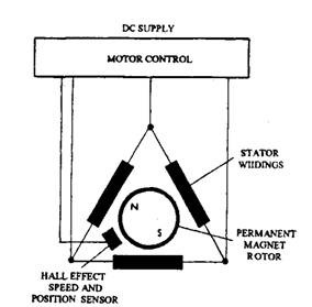
The EC motor can be considered halfway between an AC and a DC motor. Figure 34.8 represents a system. Its principle of operation is almost similar to the synchronous motor (described above), except that the rotor uses permanent magnets so that slip rings are not required. This is sometimes known as a brushless motor. A sensor operated by the rotor provides feedback to the control and power electronics. The frequency of the rotating field produced by the control system determines motor speed. When this motor is used as drive motor, the torque characteristics is such that a gearbox is needed to ensure maintenance of an efficient motor speed.

Fig. 34.7. Representation of the synchronous motor.

Fig. 34.8. Electronically controlled motor.

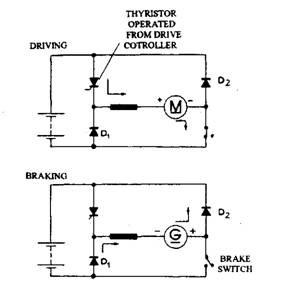
Fig. 34.9. Thyristor controlled series wound motor.
DC Motor.
The DC motor is well proven device and has been used for many years on electric vehicles. The main disadvantage of this motor is that a high current is required to flow through the brushes and commutator.
DC Series Wound Motor.
The main advantage of this motor is that it provided high torque at low speeds. Figure 34.9 shows the control of a series wound motor using a thyristor. Also the figure illustrates how it can provide simple regenerative braking.
DC Separately Existed Shunt Wound Motor.
The fields can be controlled either by using an additional resistance or chopper control in order to vary the speed. By using a suitable controller the start up torque can be solved. By increasing field strength at the appropriate time this motor is also suitable for regenerating braking. Some EV drive system vary the field power only for normal driving, but this causes a problem at slow speeds because of the high current.
