20.6.
Cylinder Servicing
Block Condition.
Block abnormalities occur in the cylinder wall, cooling system and shaft bore alignment, and as broken parts. All of the other engine parts depend upon the block for support, alignment, and operating environment.
Cylinder wall wear (Fig. 20.38) is one of the most visible block conditions, caused by a wrongly installed oil control ring. Cylinder walls, in normal use, become smooth and glazed from the burnishing effects of the piston and rings during operation even if taper, out-of-round, and wavy wall conditions exist. Dirt and

Fig. 20.38. A badly scored cylinder wall.
broken rings produce scratches on the wall. The presence of scratches allows oil to enter into the combustion chamber on the intake stroke and combustion gases to blow into the crankcase during the power stroke.
Occasionally, the connecting rod strikes the bottom edge of the cylinder wall as the piston and rod assembly are removed or installed. This nicks the bottom edge of the cylinder and raises sharp points. If these points are not removed, they scratch the piston skirt as shown in Fig. 20.39.
Piston pin locks, if project out of the piston surface, normally scores the cylinder wall. If the piston pin drifts out of its bore, it too, scores the wall. If the oil ring spacer is overlapped, it scores the cylinder wall. Occasionally, deep scores are produced, which break into the coolant jacket. To handle this situation, a thin-walled cast iron sleeve can be installed. The cylinder is bored oversize to a diameter to accept the sleeve. Then the sleeve is pressed in and bored to the required cylinder diameter.
The cooling system may be plugged with deposits or, in unusual cases, may be miscast when a casting core was damaged. The water jacket should be thoroughly checked. Core plug openings should be checked for any leakage.
During operation, the block is stressed mechanically as well as thermally. Mechanical stress is caused due to assembly bolt torques, combustion pressures, and dynamic loads. Thermal
stress due to combustion heat may cause the block to warp and take a set. The block must be checked for parting surface flatness, especially the head deck, and for shaft bore alignment. Misalignment of shaft-bores can be known by the bearing distress difference between the bearing shells. Bearing bore alignment can be checked with a properly ground test arbor 0.025 mm smaller than the bearing bore that is bolted in place of the crankshaft. The block is aligned if the test arbor can be turned by hand with a 30 cm handle. Alignment may also be checked with a straightedge placed across three or more bearing saddles. A feeler gauge one half the
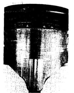
Fig. 20.39. A damaged piston skirt scored by a burr on the bottom of the cylinder.

Fig. 20.40. Checking the main bearing saddle alignment with a straightedge.
bearing clearances should not enter between the straightedge and saddle (Fig. 20.40). If it goes, then warpage exists.
Cracks in the block cause leakage or d|0 not support engine loads. Some cracks are repairable, but the location of the crack and cost of repair determine whether to repair or replace the block. Cracks on the exterior portion of the coolant jacket are usually repairable. Cracks in main bearing webs are not repairable.
Block Cleaning and Core Plug Installation.
Cleanliness is extremely important during the engine rebuilding. Engine blocks, cylinder heads, and other engine components are generally cleaned in a hot soak tank. The core plugs are removed from the block before cleaning. Some oil galleries have threaded plugs, which are also removed to permit dirt to escape. The components should be steam cleaned after they are taken out from the hot soak tank. All passages in the block should be blown out with compressed air. New core plugs are installed and threaded plugs are reinstalled when cleaning is completated. Core plug openings should be lightly coated with room-temperature vulcanizing (RTV) sealer before the core plugs are fitted. Figure 20.41 illustrates the correct procedure for core plug installation.
Cylinder Measurement.
Engines in front wheel drive cars generally operate at higher rpm than the engines in rear wheel drive cars. Therefore, it is necessary to make precision measurements and conduct accurate machining operations when these engines are serviced. Cylinders should be measured for wear and out-of-round with a bore gauge. The cylinder is measured at,
(i) 10 mm from the top of the ring travel, (H) Centre of the cylinder wall, and
(Hi) 10 mm above the bottom of the ring travel.
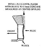
Fig. 20.41. Core plug installation.
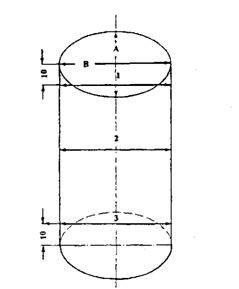
Fig. 20.42. Cylinder measurement locations.
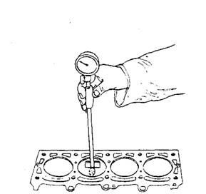
Fig. 20.43. Cylinder measurement with a bore gauge.
The cylinder should also be measured at points A and B shown in Fig. 20.42 at all three locations to determine the out-of-round. If the cylinder taper or out-of-round exceeds the manufacturer’s specifications, the cylinder must be re-bored before new rings are fitted. Figure 20.43 illustrate the measurement of a cylinder with a bore gauge.
Cylinder Reconditioning and Reboring.
A ridge reamer is normally used to remove the ring ridge from the top of the cylinder before the pistons are removed. Care must be taken to remove the ring ridge without marking the cylinder wall. If the cylinder taper and out-of-round is within specifications, at 220-grit deglazing hone is used to deglaze the cylinder without removing any metal. Cylinder re-boring can be performed with a cylinder hone, a boring bar, or an automatic cylinder-resizing machine. Many engine-rebuilding shops use automatic cylinder resizing machine.
Irrespective of the cylinder resizing method, the cylinder finish is extremely important to have proper oil control and long life of piston ring. The maximum cylinder wear takes place at the top of the ring travel because this area, where the least amount of lubricating oil is available, is subjected to the highest pressure. Once a cylinder has been resized, it must fulfil the following conditions.
(i) The cylinder diameter must be correct, and the piston-to-cylinder clearance must meet
the manufacturer’s specifications. (H) The cylinder must not have taper and out-of-round.
(Hi) The cylinder surface must have a finish to provide proper oil control and long piston ring life.
Proper finish of the cylinder walls holds enough oil to lubricate the piston rings and prevent piston and ring scuffing, especially during the engine break-in period. The oil film on the cylinder walls also provides a seal, which minimizes “blow-by” from the combustion chamber to the crankcase. A cylinder with too rough finish causes premature ring wear. If the cylinder finish is too smooth, the ring does not seat properly and “blow-by” becomes excessive due to an insufficient oil film on the cylinder walls. Also with too rough or too smooth cylinder finish, oil consumption may be excessive.
Before the cylinders are resized, the pistons should be measured at the location shown in Fig. 20.44. The piston size may vary slightly in a set of pistons, and the smallest piston should be used first when the pistons are fitted to the cylinders. If the piston measurement is 87.442 mm and the piston-tip-cylinder clearance is 0.0.381 mm, the finished cylinder size must be 87.4435 mm.
To avoid block distortion, the main bearing caps are installed and torqued to specified values prior to the honing of the cylinders. Initially, coarser stones are used to hone the cylinder to within 0.076 mm of the finished cylinder size. Finer stones are then used to bring the cylinder to the exact size and provide the proper cylinder wall finish. A honing stone contains thousands of very small cutting edges, which leave a multitude of criss-cross grooves in the cylinder wall. Millions of miniature diamond-shaped areas are thus formed on the cylinder walls, which
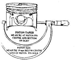
Fig. 20.44. Piston measurement.
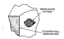
Fig. 20.45. Crosshatch cylinder honing pattern.
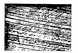
Fig. 20.46. Crosshatch cylinder honing pattern magnified 100 times.

Fig. 20.47. Cylinder finish measured in micro-millimetre.
maintain an oil film on the wall, and the piston rings ride on this film. The criss-cross grooves in the cylinder wall are referred to as Crosshatch. A Crosshatch pattern on a cylinder wall, shown in Fig. 20.45, is magnified to 100 times in Fig. 20.46.
The surface finish produced by the honing stone depends also upon the cutting pressure. A finer finish is attanined with reduced cutting pressure, and a rougher finish with excessive pressure. If excessive pressure is applied, the stones wear rapidly and become loaded with metal residue from the cylinder walls so that an irregular burnished finish results. A specific distance, referred to as plateau, should be maintained between the Crosshatch grooves. The depth of the Crosshatch grooves is measured with an instrument that records the distance in micro-millimetres (Fig. 20.47) between the peaks and the valleys produced by a stylus, moved across the cylinder finish. This instrument indicates the average peak-to-valley depth, which is about one third of the actual peak-to-valley depth because of surface irregularities.
A satisfactory cylinder finish indicates the following. (i) The Crosshatch angle of 45 of 65 degrees is measured at the centre of the cylinder. (ii) The Crosshatch pattern is uniformly cut in each direction.
(Hi) The Crosshatch finish is clean-cut without sharp edges, and free fronr torn or folded metal.
(iv) The surface finish reading should be 71 to 89 micro-millimetres, using the arithmetic average (AA) method.
(v) The plateau should be one-half to two-thirds of the surface height.
(vi) The cylinder finish must be free of burnish, glaze and embedded particles.
The specifications of the cylinder finish vary depending on the type of piston rings used. After the required cylinder size and finish are obtained, the cylinders are thoroughly cleaned. A lint-free cloth coated with lubricating oil should be used for cleaning. The pistons must be fitted individually to each cylinc – d then they should be marked so that they are always assembled in the correct cylinder.
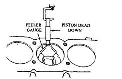
Fig. 20.48. Measuring piston-to-cylinder clearance with a feeler gauge.
The piston-to-cylinder bore clearance is measured with a feeler gauge. The piston is positioned upside down in the cylinder, with the piston notch toward the front of the engine. A feeler gauge of the specified thickness is inserted between the piston skirt and the cylinder wall, and then the gauge is attached to pull scale (Fig. 20.48).
The feeler gauge thickness for many gasoline engines is 0.0381 mm, but the manufacturer’s specifications must be given priority. When the piston is held in the cylinder, the pull required to remove the feeler gauge should be 27 to 54 N.
