13.8.
Charging the Battery
During charging all the sulphate is driven out of the plates and returned to the electrolyte. To achieve this, a direct current is passed through the cell in the opposite direction to that of discharging. During recharge, the lead sulphate (P0SO4) in the positive plate is converted into lead peroxide (Pb02) while the lead sulphate in the negative plate is converted into spongy lead (Pb). Sulphate from the plates combines with the hydrogen (H2) in the water to form sulphuric acid (H2SO4) so that the electrolyte gradually becomes stronger until all the sulphate absorbed by the plates during discharging has been returned to the electrolyte.
The manufacturer’s recommendation for recharging of battery varies slightly. During recharging the same ampere hour capacity must be put back as was used on discharge plus a little addition to take care for losses. Therefore the main question about charging is not how much but at what rate.
As per the earlier recommendation the battery should be charged at a tenth of its ampere hour capacity for about 10 hour or less. This is based on assumption that the ampere hour capacity is quoted at the 20 hour rate, because a tenth of this figure makes an allowance for the charge factor. This figure is still valid but nowadays ampere hour capacity is not always used, hence a different method of deciding the rate is at a sixteenth of the reserve capacity, again for up to 10 hours. Another way is to set a charge rate at one fortieth of the cold start performance figure, also for up to 10 hour. If a battery is already half charged, half the time is required to recharge to full capacity.
The above suggested charge rates are considered as the best for prolonging battery life. They all however require a constant current charging source. A constant voltage charging system is often also considered the best way to charging a battery. This implies that the charger, an alternator on a car for example, is maintained at a constant level and the state of charge in the battery determines the rate of current flow. This is often the fastest way to recharge a flat battery. The two ways of charging are illustrated in Fig. 13.62, which represents the relationship between charging voltage and the charging current. If a constant voltage of less than 14.4 V is used then it does not cause excessive gassing and hence this method is particularly suitable for sealed batteries. The charging time is not usually recommended to be more than seven hours. Table 13.5 summarises the charging techniques for a lead-acid battery.

Fig. 13.62. Relationship between charging voltage and charging current (for two ways of charging)
Table 13.5. Charging Techniques.
| Constant voltage (14.4 V maximum) | Recharges any battery in 7 hrs or less without any risk of over-charging. |
| Constant current | Ideal rate 1/10 of Ah capacity or 1/16 of reserve capacity or 1/40 of cold start current. Charge time up to 10 hrs or pro rata original state. |
Boost charging, a popular technique of charging, is used, but not recommended as the best method. If, however, correctly administered and not repeated too often, it is suitable for most batteries. During fast or boost charging, the battery temperature should not exceed 316 K. With sealed batteries it is particularly important to avoid excessive generation of gas so that the build up of pressure is prevented. At about five times the normal charging rate, the battery attains 70-80 percent of its full charge within approximately one hour.
The power supply from the mains being an alternating current at 220 to 240 volts is unsuitable for charging batteries, and the battery charger modifies this supply to suit the battery
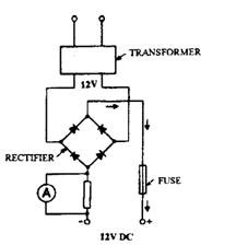
requirements. When the charger is operated from 230 V AC mains supply, the charger must incorporate a transformer to step-down the voltage to suit the battery, and a rectifier to convert AC to DC. By using a circuit to connect the diodes or metal plates in the rectifier, it is possible to obtain full-wave rectification. In Fig. 13.63 the transformer only has one voltage output, but when additional tapings of the transformer secondary coil are provided, other outputs can be obtained. (Fig. 13.64).
The battery charger, therefore, basically performs three functions :
(i) It reduces the voltage through a step-down transformer to suit the battery being charged.
(ii) It converts the alternating current to a direct current through a rectifier so that the discharging chemical reaction within the battery cells is reversed.
(Hi) It automatically adjusts the charge rate to match the state of charge of the battery.
For charging a battery, the positive lead of the charger unit is connected to the positive terminal post and the negative lead to the negative terminal post. The battery vent plugs should
be removed to allow gas to escape. The electrolyte level should be checked before charging. Batteries are connected to the charger either individually or in a balanced series parallel arrangement. In Fig. 13.65, the ‘+’ terminals of the batteries are connected to the chargerBy setting the output voltage, the total output current from the charger takes three paths. The current flow through any branch of the circuit depends on the state-of-charge of the batteries in that branch.
Batteries should never be left in a discharged state. If they are to be used occasionally, they should be periodically charged at the normal recharge rate by an independent source like a portable battery charger to prevent excessive sulphate formation on the plates.

Fig. 13.63. Layout of battery charger.

Fig. 13.64. Battery charger transformer.
