Generalized Rotations
Before we further analyze the transform properties of quaternions, it would be worthwhile to review some of the key concepts relating to general three-dimensional rotations.
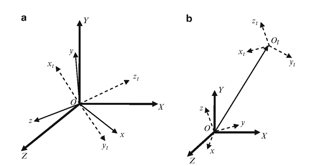
Any composite transformation that preserves length, angle and area is called a rigid-body transformation. If a rigid body transformation has also a fixed point (pivot), then it is a rotation. A rotation can be measured in terms of the angular deviation of an orthogonal right-handed system fixed on the rotating body, with the origin of the system at the fixed point of rotation. In Fig. 5.2a, Ox, Oy, Oz are the axes of an orthogonal triad before rotation, and Oxt, Oyt, Ozt denote the transformed axes directions after a rotation about O. The coordinate reference frame is inertially fixed and is represented by X, Y, Z axes.
A general rigid body transformation of an object without a fixed point can be treated as a rotation followed by a translation. Such a transformation can be equivalently performed by first carrying out a rotation that aligns the axes parallel to the final directions, followed by a translation that moves the fixed point O to its final position Ot (Fig. 5.2b). While any translation can be unambiguously represented by a three component vector, a general rotation may be specified in several ways. In the following, we consider the Euler angle and angle-axis representations of threedimensional rotations.
Fig. 5.2 (a) A generalized rotation with a fixed point O that transforms the directions of body-fixed axes from O(x, y, z) to O(xt, yt, z,t). (b) A general transformation without a fixed point
Euler Angles
The Euler’s theorem on rotations states that any general rotation can be performed using a sequence of elementary rotations about the coordinate axes passing through the fixed point. The theorem further states that if no two successive rotations is about the same axis, then the maximum number of rotations needed to achieve the transformation is three. Thus any rotational transformation can be represented by a sequence of three rotations about mutually independent axes. These angles are called Euler angles. Before defining an Euler angle representation, we need to fix the sequence in which the rotations are performed. If we denote rotations about the X-axis by f, rotations about Y by ¢, and rotations about Z by 6, a set of Euler angles can be defined using any of the following 12 sequences:
The Euler angle sequence { f ¢ 6 g represents a rotation about X followed by a second rotation about Y, followed by a third rotation about the Z axis. The sequence {p]_f ¢2g gives another Euler angle representation in terms of a rotation about the Y axis, followed by a second rotation about the X axis, and then a third rotation again about the Y axis. The six sequences where each axis is used exactly once are called proper Euler angles.
The transformation matrix for the { f ¢6 g sequence is obtained by concatenating the transformation matrices as shown below.
The above equation can be interpreted as the transformation of any point (x, y, z) to (x’, y, z!) in a fixed coordinate frame. This interpretation does not use any information pertaining to body-fixed axes. On the other hand, if we assume that x, y, z represent the body-fixed axes which initially coincide with the coordinate reference axes X, Y, Z, respectively, Eq. 5.30 can be viewed as the transformation of a point from the moving body frame to the fixed coordinate reference frame. The Euler angle representation described above (and shown in Fig. 5.3) used rotations that are performed about the fixed principal axes directions X, Y, Z of the reference frame. Such a transformation is called an extrinsic composition of rotations.
Fig. 5.3 An extrinsic composition of Euler angle rotations performed using the sequence { f, $, 6 g
Fig. 5.4 An intrinsic composition of Euler angle rotations performed using the sequence { f, $, 6 }
An intrinsic composition, on the other hand, uses rotations about body-fixed axes whose directions change in the reference frame after every rotation. For example, an aircraft orientation is defined in this manner. In Fig. 5.4, the yaw rotation f is performed about the x-axis, the roll rotation $ about the transformed body y-axis, and the pitch rotation 6 about the transformed body z-axis. For this sequence of intrinsic composition of rotations, the transformation from body frame to the coordinate reference frame is given by
Fig. 5.5 Two different Euler angle interpolation sequences generated for the same initial and target orientations
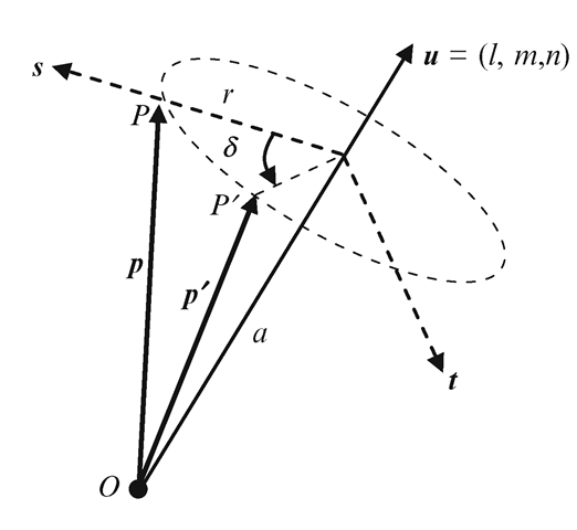
Fig. 5.6 Transformation of a vector under a general rotation about the origin in three-dimensional space
A three-dimensional orientation can be represented in different ways using different Euler angle sequences. Even if we keep the sequence fixed, certain orientations can have more than one set of Euler angles. For instance, using the same sequence { f ÿ 6}, both {—45, —80, 0} and {135, —100, —180} represent the same transformation. This can be verified by evaluating the product matrix in Eq. 5.30 for the two sets of angles. The non-uniqueness of the Euler angle representation also means that you may not get a unique interpolation path between two orientations (Fig. 5.5).
Angle-Axis Transformation
The Euler’s theorem concerning three-dimensional rotations states that any number of rotational transformations with a single fixed point applied to an object can be replaced by a single rotation of the object about an axis passing through the fixed point. The axis is often called the equivalent axis of rotation. Any orientation of an object with the origin as a fixed point can therefore be specified using an angle of rotation 1 and an axis of rotation given by a unit vector u = (l, m, n). In the following discussion, we assume that the axis of rotation passes through the origin. Figure 5.6 depicts the rotational transformation applied to a vector p (or a point P).
If we denote the projected lengths of the vector p along directions of u (axis of rotation) and s (perpendicular to axis of rotation) by a and r respectively, we can write p = au + rs, where a = p^u. During any rotation of the vector p about the axis u, both these projected distances a and r remain constant. If t denotes the vector orthogonal to both u and s, the transformed vector direction p’ can be written as
The above equation is the well-known Rodrigues’ rotation formula. The matrix version of the Rodrigues’ formula can be derived by defining a 3 x 3 skew-symmetric matrix UX as
and replacing u, p,p’ by the corresponding column vectors:
With the above notations, the vector cross-product uxp has an equivalent matrix representation (UX)p. It can also be easily verified that the term (p^u) u in Eq. 5.32 is equivalent to the matrix (UUT) p. Thus we get
Noting that
Equation 5.35 can be written in an alternate form as below.
Equation 5.35 can also be written in the expanded matrix form as follows for defining the rotational transformation of a point P expressed in homogeneous coordinates:
Let us consider the problem of computing the equivalent angle and axis of rotation from a transformation matrix. Given a general 4×4 rotation matrix in the form
we get the following equations using the matrix elements from Eq. 5.38:
From the above equations, we can derive the expressions for angle and axis of rotation as follows:
In the next section, we will establish the equivalence between an angle-axis transformation and a unit quaternion transformation of the form QPQ* where P is a pure quaternion (0, p).


![tmpc2f9-217_thumb[2] tmpc2f9-217_thumb[2]](http://what-when-how.com/wp-content/uploads/2012/07/tmpc2f9217_thumb2_thumb.png)


![tmpc2f9-220_thumb[2] tmpc2f9-220_thumb[2]](http://what-when-how.com/wp-content/uploads/2012/07/tmpc2f9220_thumb2_thumb.png)
![tmpc2f9-221_thumb[2] tmpc2f9-221_thumb[2]](http://what-when-how.com/wp-content/uploads/2012/07/tmpc2f9221_thumb2_thumb.png)
![tmpc2f9-222_thumb[2] tmpc2f9-222_thumb[2]](http://what-when-how.com/wp-content/uploads/2012/07/tmpc2f9222_thumb2_thumb.png)
![tmpc2f9-224_thumb[2] tmpc2f9-224_thumb[2]](http://what-when-how.com/wp-content/uploads/2012/07/tmpc2f9224_thumb2_thumb.png)
![tmpc2f9-226_thumb[2] tmpc2f9-226_thumb[2]](http://what-when-how.com/wp-content/uploads/2012/07/tmpc2f9226_thumb2_thumb.png)
![tmpc2f9-227_thumb[2] tmpc2f9-227_thumb[2]](http://what-when-how.com/wp-content/uploads/2012/07/tmpc2f9227_thumb2_thumb.png)
![tmpc2f9-228_thumb[2] tmpc2f9-228_thumb[2]](http://what-when-how.com/wp-content/uploads/2012/07/tmpc2f9228_thumb2_thumb.png)
![tmpc2f9-229_thumb[2] tmpc2f9-229_thumb[2]](http://what-when-how.com/wp-content/uploads/2012/07/tmpc2f9229_thumb2_thumb.png)
![tmpc2f9-230_thumb[2] tmpc2f9-230_thumb[2]](http://what-when-how.com/wp-content/uploads/2012/07/tmpc2f9230_thumb2_thumb.png)
