Barycentric Coordinates
The barycentre of a rigid body is its centre of mass. For a triangle, the barycentre is its centroid. Given vertices P1, P2, P3 of a triangle, the centroid C can be easily computed as the average of the vertex coordinates (P1 + P2 + P3)/3. Thus C can be represented as a convex combination of the vertex points. Indeed, Eq. 2.45 has just shown that any point Q inside the triangle could be expressed as a convex combination of vertices. If we re-write Eq. 2.45 as
then the point Q is uniquely specified by a new set of coordinates (A1, X2, A3) defined by P1, P2, and P3. This local coordinate system is called the barycentric coordinates for the triangle. Barycentric coordinates are also sometimes referred to as trilinear coordinates. From Eq. 2.46 we see that the vertices themselves have barycentric coordinates given by
As seen earlier, the centroid C has barycentric coordinates (1/3, 1/3, 1/3). The barycentric coordinates of a point Q with respect to P1, P2, P3 have a geometrical interpretation as the ratios of the areas of triangles QP2P3, QP3P1, QP1P2 to the area of the triangle P1P2P3. In the following equations, the symbol A denotes the signed area of a triangle:
The barycentric coordinates given in Eq. 2.48 are unique for every point on the plane of the triangle. They can be directly used to get the interpolated value of any quantity defined at the vertices of the triangle. If fP1, fP2, fP3 denote the values of some attribute associated with the vertices, then the interpolated value at Q is given by
Fig. 2.12 A one-to-one mapping of points from one triangle to another can be obtained using barycentric coordinates
Using barycentric coordinates we can establish a one-to-one mapping of points from within one triangle to another. For any given interior point Q of the first triangle, we compute the barycentric coordinates. The linear combination of the vertices of the second triangle with the barycentric coordinates of Q gives the coordinates of the corresponding point R inside the second triangle (Fig. 2.12). We can use this mapping to transfer values from the interior of the first triangle to the second. As an immediate application of this transfer, we can map an image (or texture) from one triangle to another.
In a simplified two-dimensional case where P1 = (x1, y1), P2 = (x2, y2), P3 = (x3, y3), Q = (xq, yq), the expressions for the barycentric coordinates of Q given in Eq. 2.48 assume the following form:
If any of the above quantities is negative, then the point Q lies outside the triangle P1 P2P3. Thus barycentric coordinates find applications in point inclusion tests. In a general three-dimensional case, however, the area of a triangle computed using Eq. 2.3 would always be positive, and correspondingly the area ratios in Eq. 2.48 would also be positive. As previously discussed in Sect. 2.2, the computation of signed areas of triangles requires a view vector w. Since we need this vector to be fixed with respect to every triangle in Eq. 2.48, we can conveniently choose w = (P2—P1) x (P3—P1). Now the barycentric coordinates A1, A2 and A3 in Eq. 2.48 can be computed by applying the formula in Eq. 2.8 to each of the triangles QP2P3, QP3P1, QP1P2 and P1P2P3. If the conditions X1 + X2 + X3 = 1,0 < A1, A2, A3 < 1 are met, then Q lies on the plane defined by the points P1, P2, P3, and also lies within the triangle P1P2P3. Note that in the most general case, the point Q need not be on the plane of the triangle. Hence we require the additional condition that the sum of barycentric coordinates equals 1 to ensure that the points are coplanar.
Barycentric coordinates are also useful for finding the centre of a circle that passes through three non-collinear points, P, Q, R in three dimensions. Denoting the vectors along the sides of the triangle by a = Q—P, b = R—Q, and c = P—R, the barycentric coordinates of the centre of the circle are
The centre of the circle is then given by the following linear combination of the three points:
In the following section, we will look at the application of vectors in the Phong-Blinn illumination model used for lighting calculations in the OpenGL pipeline.
Basic Lighting
The hardware accelerated lighting model that is traditionally used in Computer Graphics applications is based on Phong-Blinn approximation for an omnidirectional point-light source. A local illumination model that does not account for complex effects such as reflections, refractions, shadows and indirect illumination is found to be generally adequate for a majority of graphics applications. In this model, light-material interaction is simply modelled using a component-wise multiplication of material colour and light colour. We can represent colour by a vector comprising of red, green and blue components as c = (r, g, b, 0). This vector model can be further generalized by replacing the fourth component by k that represents the transparency (or opacity) term which can take non-zero values. In the discussion that follows, ma, md, ms denote respectively the ambient, diffuse and specular components of material colour, and Ia, Id, Is the corresponding components of the light source. Each of these colour components is typically a 3-tuple consisting of red, green and blue values. For notational convenience, we represent ma by the vector (rma, gmci, bmci), Ia by the vector (ria, ga, ba), and so on.
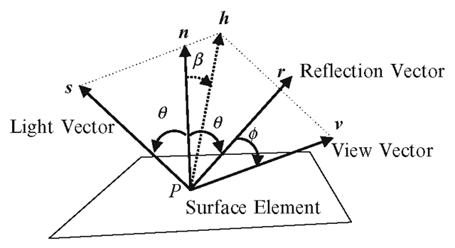
Fig. 2.13 Important vectors and angles between them, used in lighting calculations
The ambient light-material interaction is then modelled by the component-wise vector product
Figure 2.13 shows the geometry of unit vectors used for computing diffuse and specular reflections from a surface. From a point P on a surface, s denotes the unit vector towards the light source, n the unit surface normal vector, and v the unit vector towards the viewer. The perceived intensity of reflection at the viewer’s position varies with changes in the angles between these vectors. The variations in diffuse and specular reflections are represented by multiplicative factors kd and ks respectively. According to the Lambertian reflectance model, the intensity of diffuse reflection from a surface is uniform in all directions, and varies as the cosine of the angle 6 between the light source vector s and the surface normal vector n, and is therefore proportional to s*n. If the angle between the two vectors is greater than 90°, the normal vector faces away from the light source vector, and the surface is in shadow. In such a situation, the value of kd must be set to 0. We therefore have the following view-independent factor for the diffuse term:
The specular reflection factor ks is computed as a function of the cosine of the angle ¢ between the direction of unit specular reflection r given by Eq. 2.5 and the unit view vector v, with an exponent f known as the shininess term or the Phong’s constant. The exponent is useful in controlling the overall brightness and the concentration of the specular highlight.
The Blinn’s approximation eliminates the need for computing the specular reflection vector using Eq. 2.5 by defining a unit vector h along the direction s + v. This vector is called the half-way vector. If n*h = cosß, then equating the angles on either side of h gives
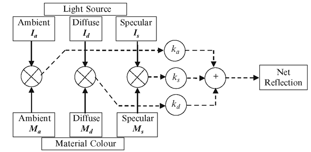
Fig. 2.14 Schematic of the calculations performed in a basic lighting model
From the above equation we find that ¢ = 2ß. The term r*v in Eq. 2.55 can therefore be replaced with nh by absorbing the factor 2 in ks. This gives theBlinn’s approximation for ks:
A schematic of the lighting computation using the Phong-Blinn illumination model outlined above is given in Fig. 2.14.
Summary
This topic reviewed some of the geometrical computations involving points, lines, planes, triangles and curves, that are fundamental to many algorithms in computer graphics. Important concepts such as homogeneous coordinate representation of points, signed angles, signed areas of triangles, and barycentric coordinates were outlined. Equations relating to affine transformations and affine combinations of points were discussed. This topic also gave the equations for a basic lighting model consisting of ambient, diffuse and specular components of reflection.
The next topic introduces a hierarchical structure that is useful for modelling transformations applied to articulated models and other similar objects containing interconnected parts.
![tmpc2f9-75_thumb[2][2]_thumb tmpc2f9-75_thumb[2][2]_thumb](http://what-when-how.com/wp-content/uploads/2012/07/tmpc2f975_thumb22_thumb_thumb.png)
![tmpc2f9-76_thumb[2][2]_thumb tmpc2f9-76_thumb[2][2]_thumb](http://what-when-how.com/wp-content/uploads/2012/07/tmpc2f976_thumb22_thumb_thumb.png)
![tmpc2f9-77_thumb[2][2]_thumb tmpc2f9-77_thumb[2][2]_thumb](http://what-when-how.com/wp-content/uploads/2012/07/tmpc2f977_thumb22_thumb_thumb.png)

![tmpc2f9-79_thumb[2][2]_thumb tmpc2f9-79_thumb[2][2]_thumb](http://what-when-how.com/wp-content/uploads/2012/07/tmpc2f979_thumb22_thumb_thumb.png)
![tmpc2f9-80_thumb[2][2]_thumb tmpc2f9-80_thumb[2][2]_thumb](http://what-when-how.com/wp-content/uploads/2012/07/tmpc2f980_thumb22_thumb_thumb.png)
![tmpc2f9-81_thumb[2][2]_thumb tmpc2f9-81_thumb[2][2]_thumb](http://what-when-how.com/wp-content/uploads/2012/07/tmpc2f981_thumb22_thumb_thumb.png)

![tmpc2f9-83_thumb[2][2][2] tmpc2f9-83_thumb[2][2][2]](http://what-when-how.com/wp-content/uploads/2012/07/tmpc2f983_thumb222_thumb.png)
![tmpc2f9-84_thumb[2][2][2] tmpc2f9-84_thumb[2][2][2]](http://what-when-how.com/wp-content/uploads/2012/07/tmpc2f984_thumb222_thumb.png)
![tmpc2f9-85_thumb[2][2][2] tmpc2f9-85_thumb[2][2][2]](http://what-when-how.com/wp-content/uploads/2012/07/tmpc2f985_thumb222_thumb.png)
![tmpc2f9-86_thumb[2][2][2] tmpc2f9-86_thumb[2][2][2]](http://what-when-how.com/wp-content/uploads/2012/07/tmpc2f986_thumb222_thumb.png)

![tmpc2f9-88_thumb[2][2][2] tmpc2f9-88_thumb[2][2][2]](http://what-when-how.com/wp-content/uploads/2012/07/tmpc2f988_thumb222_thumb.png)
