23.2
In today’s IP telephony world, most of the IP telephone service providers (such as Vonage, AT&T Callvantage, and ViaTalk, etc.) operate in partially closed environment and are

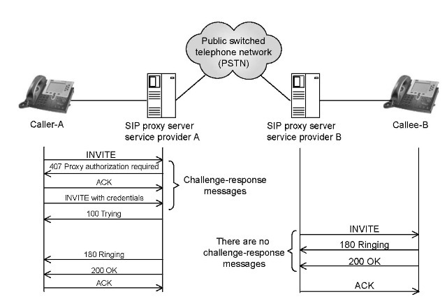
FIGURE 23.1 SIP proxy server authenticates a caller.
connected to each other through the Public Switched Telephone Network (PSTN) as shown in Figure 23.1. For example, let us assume that User A and B belong to two different VoIP service providers A and B, respectively. Though the service providers use IP networks to connect with their users, still the calls between User A and B are expected to traverse the PSTN somewhere in the middle. In an island-based VoIP deployment, the IP traffic is translated into the SS7 traffic [5] (for the transportation over the PSTN) and then back into the IP traffic. It is expected that as VoIP adoption grows the VoIP service providers will interconnect through the peering points.
23.2.1
Lack of Authentication between Callee and Inbound SIP Proxy Server
As shown in Figure 23.1, the subscriber A’s call request is received by the outbound SIP proxy server A. The proxy server is an application-layer router that forwards SIP requests toward its destination user agents (UAs). Besides facilitating the communications between UAs, SIP proxies are also useful for enforcing policy. Being an important network element in the creation and management of multimedia communication sessions between clients, the SIP proxy servers are always under threats from malicious users and hackers. Consequently, most of the security efforts are focused on securing it from various attacks. The IP telephone service providers ensure that only authenticated users are authorized to use the SIP proxy server resources. Each of the received INVITE requests are challenged by sending 401 Unauthorized or 407 Proxy Authentication Required messages back to the callers. However, as we observe in Figure 23.1, there are no such authentication mechanism (e.g., challenge-response messages) between the call recipient (i.e., callee-B) and his/her inbound SIP proxy server B. Therefore, malicious users capable of capturing SIP signaling messages between the SIP proxy server and its subscribers can launch various attacks on the call recipients.

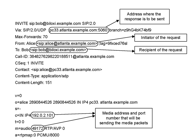
FIGURE 23.2 Structure of an INVITE message.
23.2.2
Exploitation of Call Setup Request (INVITE) Message
Before discussing the exploitation of an INVITE message, we describe its message structure and the purpose of various header fields. As shown in Figure 23.2, the Via header field contains the address where the caller is expecting to receive the response messages of this request, the From and To header fields contain SIP URIs of the caller and callee, respectively. The Call-ID is a globally unique identifier for this call and the Contact field contains direct route information to reach the caller. The invite’s header fields and message body are separated by a blank line. The session description such as media type, codec, and sampling rate etc. are contained in INVITE’s message body. The connection information field (i.e., c=) contains media connection information such as media’s source IP address that will send the media packets. Similarly, the media information field (i.e., m=) contains media type and the port number.
The exploitation of INVITE message is based on abusing connection information field contained in the INVITE message body. The SIP proxy server remains at INVITE header level and routes this message towards the callee without inspecting message body. The callee’s SIP UA parses and interprets the INVITE message and records media IP address and port number mentioned in the c= and M= fields, respectively.* After a SIP session is established, the callee sends audio packets towards this media IP address and port number. By spoofing the connection information field, an attacker can redirect the media stream towards the spoofed (victim) IP address and port number [4].
