Call establishment
The call can be established only if the MS is ON and successfully registered in a network by the location update procedure, as explained in the previous section. There are two different scenarios for call establishment, i.e., mobile originated call (MOC) and mobile terminated call (MTC).
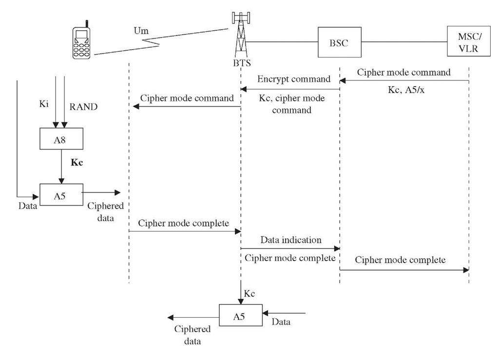
Figure 3-22 Cipher mode procedure.
Mobile originated call. Figures 3-23, 3.24, and 3-25 show the signaling flow within the BSS and the NSS for a mobile originated call. In this example, the called party is a fixed line subscriber.
When a mobile subscriber keys in the destination number, using the keypad and pressing the SEND/OK button, the MS attempts to establish a radio connection with the BTS by sending a channel request on a RACH. The channel request message contains a parameter indicating to the BTS the reason for the channel request, i.e., MOC in this case. The BTS, on receiving the channel request message, adds some radio-related information and sends a channel required message to the BSC.
Figure 3-23 MOC-BSS procedures.
Figure 3-24 MOC-BSS procedures.
The BSC instructs the BTS to reserve a channel by sending the channel activation message. The BTS reserves the channel and sends a channel activation acknowledge message to the BSC. The BSC then activates the previously reserved channel by sending immediate assignment command to the BTS, which passes this message, using AGCH, to the MS. Now the MS initiates establishment of a Layer 2 connection by sending a LAPDm SABM frame, which also contains a CM service request.
The MS identifies itself by either IMSI or TMSI, which are parameters within the CM service request message. The BTS confirms the Layer 2 connection by a UA frame. At the same time, the BTS passes a CM service request to the BSC.
Figure 3-25 MOC-NSS procedures.
The BSC establishes an SCCP connection to the MSC by sending a connection request. This message also contains the CM service request received by the BTS. However, the BSC adds a few additional parameters such as LAC and CI.
The MSC confirms the logical connection by sending an SCCP connection confirmed message. The MSC may decide to authenticate the MS at this time. It sends the authentication request message over the established SCCP connection to the BSC, which transparently passes this to the MS via the BTS. The authentication request message contains two important parameters: a 128-bit random number (RAND) and a 3-bit ciphering key sequence number (CKSN). The SIM within MS uses Ki, which is stored in the SIM, and RAND to calculate the signed response (SRES) according to the A3 algorithm. The MS sends the SRES value as a parameter within the authentication response message to the MSC/VLR.
The VLR compares the SRES received from the MS to the SRES value available with it as a result of the previous send authentication procedure with the HLR/AuC. The MS is successfully authenticated if the two values match.
In networks where ciphering is not enabled, the MSC sends a CM service accept message to the MS. If ciphering is enabled, the ciphering mode procedure is initiated by the MSC.
In networks where IMEI check is ON, the MSC/VLR invokes the identity request procedure, as described in the previous section.
For security purposes, the MSC may assign a new TMSI to MS by using the TMSI reallocation command.
The MS now sends a setup message transparently to the MSC via the BTS and BSC, using the previously established logical connection. The MSC processes the information contained in the setup message. The most important parameter in the setup message received from the MS is the called party number. The MSC analyses the called party number, creates an ISUP IAM message, and sends it to the destination switch in order to establish the connection. The call proceeding indication, which is a response from the destination exchange on receiving IAM, is passed back to the MS transparently.
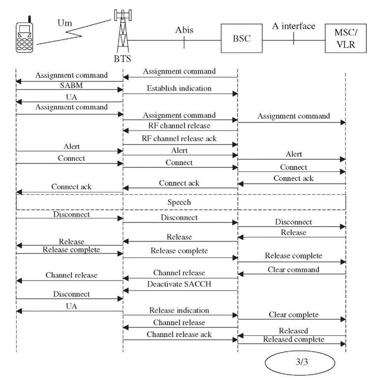
It should be noted that no speech channel is assigned on the radio interface for this call so far. This is to save the radio resources. Now only the MSC triggers the process to assign speech channel for this call. The MSC informs the BSC of the speech channel that is to be used on the A interface, using the assigned request command. The BSC then requests the BTS to reserve a traffic channel (TCH) on the air interface, using the channel activation message. On receiving a channel activation acknowledgment from the BTS, the BSC sends an assignment command to assign traffic channel. The MS and the BTS establish Layer 2 connection for the assigned channel by exchanging LAPDm SABM and UA frames. The BTS establishes Layer 3 connection by sending an assignment complete message. As the previously established control channel is no more required, the BSC releases the channel by sending a channel release message.
On receiving the ISUP ACM message from the destination exchange, indicating the a connection is being set up to the called party, the MSC sends an alert message to the MS. This results in a call progress tone being fed to the MS. The destination exchange sends an ISUP ANM message to the MSC when the called party answers. The MSC sends a connect message to the MS transparently. On receiving a connect acknowledgment, the MSC initiates charging the MS for the call.
The call is released by the MSC on receiving either an ISUP REL message from the destination exchange or a disconnect message from the MS. The MSC releases all the resources as indicated in the procedures.
Mobile terminated call. In the example shown here, the call is originated from a fixed line network. The procedures and call flow will essentially remain the same if the call is originated from another PLMN or even from the MS belonging to the same PLMN. The call is routed to the GMSC through a national network point of interconnects (POI) or through an international gateway on the basis of MSISDN, which is an international number and uniquely identifies a PLMN subscriber.
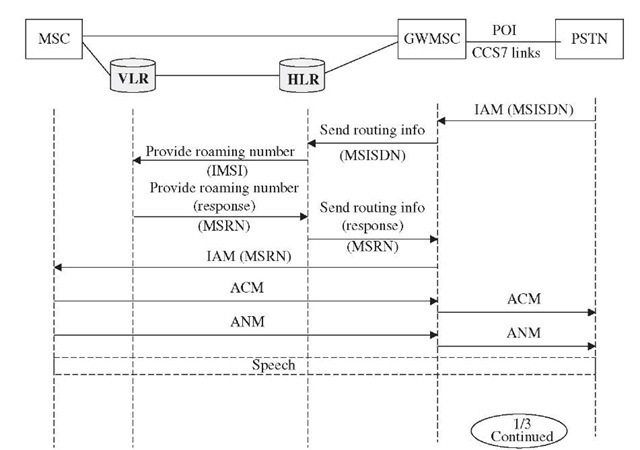
The main task of the NSS, as shown in Figure 3-26, is to find the location of the called party (current serving MSC/VLR) and the temporary identity assigned to the called MS, i.e., MSRN. Once these are known, the incoming call can be routed. The GWMSC has no means to find out where the called MS is. It needs help from the HLR, which is constantly getting updated on MS location as a result of the update location procedure. As shown in Figure 3-26, the GWMSC requests the HLR to get this information using a send routing info message. The MSISDN is used to identify the called subscriber. The HLR searches for a MSISDN entry in its record, retrieves the address of the current serving MSC/VLR and the address of the IMSI. The HLR then initiates the provide roaming number procedure toward VLR. The VLR assigns a temporary number, i.e., MSRN for routing purposes and provides this number to the requesting HLR.
Figure 3-23 MOC-BSS procedures.
On receiving the MSRN from the VLR in the provide roaming number response message, the HLR forwards the MSRN to the GWMSC in a response message to the previously received send routing info. Now the GWMSC has all the necessary information to route the incoming call to the called MS. It sends an ISUP IAM message to the serving MSC. The MSRN received from the VLR is passed as the called party number parameter within the IAM message (Figure 3-26).
When the MSC receives an IAM from the GWMSC, it queries the VLR to get the location area identity (LAI) of where the MS is currently roaming and invokes the paging procedure (Figure 3-27).
On receiving the paging request, the MS requests the BSC to assign a control channel. The call flow (see Figures 3-27 and 3-28) from this point onwards is same as described in the previous section.
Figure 3-23 MOC-BSS procedures.
Figure 3-28 BSS procedures.


