Introduction
Light detection and ranging, or LIDAR, uses the same principles as radar, but its shorter wavelengths make the data useful in quite different ways. There are a variety of LIDAR types; the form of interest here are those designed for remote sensing of the Earth. Other configurations are useful for studying the atmosphere, and in particular aerosols and dust in the atmosphere.
A typical LIDAR system consists of a laser, typically operating in the near infrared (~1.05 ^m), a scan mirror to sweep the laser beam cross-track, and a detector designed to measure the return time with an accuracy of a few nanoseconds. The returning light pulse is observed with range gates, that is, the detector is sampled in a time sequence, and those times correspond to range.
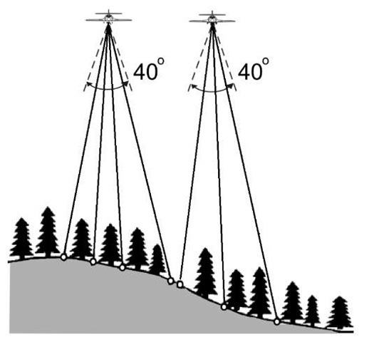
Figure 9.9 A pulse of laser light is emitted from the aerial platform. A sensor records the returning energy as a function of the xy position, providing then the z, or elevation component. Such systems are occasionally designated 3D imagers. The imager depends on a very accurate knowledge of the platform position, generally obtained from GPS.
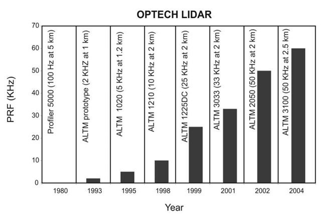
Airborne systems currently fly at modest altitudes (a few thousand feet), and the laser forms a spot on the ground of less than a meter in diameter, perhaps only a few tens of centimeters. (The beam divergence is typically a few tenths of a milliradian.) The sensor orperates in a ‘whisk-broom’ mode, sweeping cross-track with an angular extent defined by the hardware capabilities, but on the order of the -40 ° range illustrated here in Fig. 9.9. The spacing between pulses is typically larger than the spot size—typically 1-3 m. Pulse-repetition frequencies (PRF) determine the sweep rate (and angular range) which is practical for a given sensor. Initial rates were rather low. The chart below shows the evolution of the Optech sensors. The PRF being used depends somewhat on the altitude of the flying platform, so the specifications depend on altitude. Optech has manufactured most of the commercial systems in use today, so this chart reflects the field as a whole rather well. As the PRF goes up, the cost of flying a given area decreases. In a recent commercial effort, a 10 km x 20 km area north of Monterey was imaged in about a day of flying. By contrast, a Quickbird image of this area takes approximately 8 seconds to acquire.
Figure 9.10 Evolution of the Optech sensors
As with radar, fine range (altitude) resolution depends on the pulse length, at first glance. As with radar, the pulse length is really too long in time to give the sort of resolution (cm), that modern systems need to provide. As a consequence, the LIDAR systems are designed to capture the leading edge of the light pulse, which can be resolved to very high temporal resolution.
OPTECH: Airborne Laser Terrain Mapper (ALTM)
The ALTM is a terrain-mapping system for rapid, digital, elevation-data generation. A recent model generates up to 50,000 dual elevation measurements every second. As a marker for the market, in early 2004 Optech sold their fiftieth ALTM system. Other Optech products are designed for bathymetry, and use lasers modified to work in the blue-green, which is necessary for laser energy to penetrate water. The ALTM 3033 is shown in Fig. 9.11.
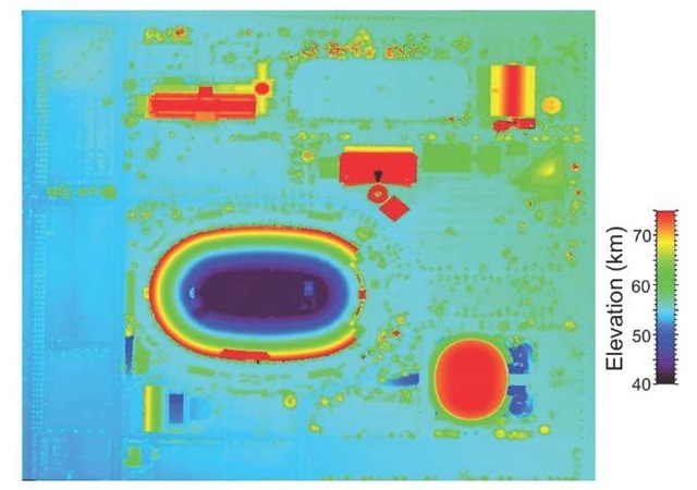
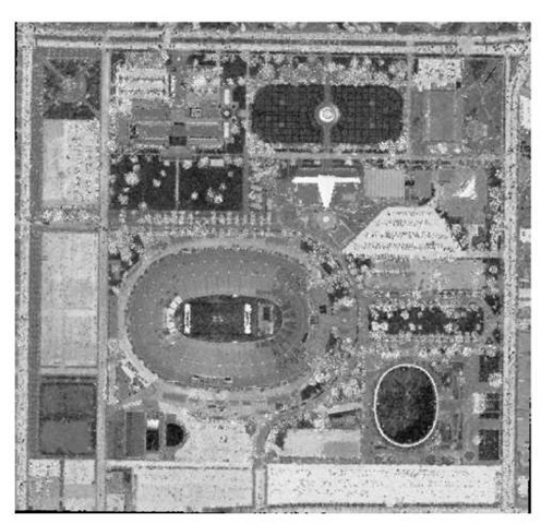
Several images from an Optech system are shown next. Data were acquired by Airborne 1 Corporation, flying over Exposition Park in Los Angeles, imaging the Coliseum and the Sports Arena (the ellipse to the lower right, Fig. 9.12). Figure 9.13 shows a horizontal transect through the scene, roughly along the long center line of the football stadium. The sloping stadium walls lead down to a field that is below the level of the ground outside the stadium. Temporary seats (bleachers) have apparently been set up in the peristyle end of the stadium. The intensity image from the 1.06-^m laser is shown in Fig. 9.14.
Figure 9.11 The ALTM 3033 fits fairly comfortably in a small airplane. The laser is a diode-pumped Nd YAG, producing a near-IR beam at a 1064-nm wavelength. The output energy depends on pulse rate, but fewer than 7 watts or 100 microJoules/pulse with a less than 12-ns pulse width.
The receiver is a single avalanche photon detector (APD).
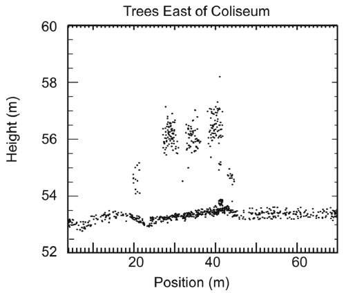
In Fig. 9.15, the scattered returns from throughout the canopy show how the laser penetrates through the leaves, reaching the ground and returning.
One of the more vexing problems in remote sensing is power and telephone lines, which are generally sub-pixel for any reasonable detector—the wires simply do not show up in optical imagery. The LIDAR, with a relatively small spot size, illuminates the wires at a fairly regular interval, and Fig. 9.16 shows the wires detected against quite accurately.
Figure 9.12 Los Angeles Coliseum, digital elevation model.
Figure 9.13 LIDAR taken over the Los Angeles Coliseum. Note the goal posts are 120 yards apart. Bleachers are at the 420 m mark. Data courtesy of Airborne 1, Los Angeles, Ca.
Figure 9.14 Intensity image from LIDAR active illumination at 1.06 ^m.
Figure 9.15 Detailed view of First/Last returns, bare soil, and extracted feature returns over a few trees to the west of the Coliseum.
Bathymetry
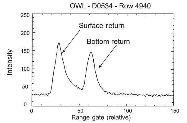
One powerful capability offered by LIDAR is the ability to survey for water depth, that is, to conduct bathymetric surveys. An older system, the ocean-water LIDAR (OWL) was flown in the early 1990s. NPS student Charles Cassidy worked on this topic in 1995. An illustration of the sort of data obtained by this sensor is given in Fig. 9.17. The sensor detects light reflected from the surface, then the bottom. The difference gives a very accurate depth measure.
Figure 9.16 Power lines in three sections of corridor, in profile mode. Individual laser data points on wires, towers, and ground are clearly distinguished. Trees are clearly visible. Product: ALTM 1020 Location: Toronto, Canada. Altitude: 380 m AGL Laser Pulse Freq.: 5 kHz9
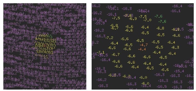
Figure 9.18 shows the results from a modern Optech system. The water depth is about 16.5 m. A cube has been placed in the water, and a smaller target placed on top of that. The figure illustrates the ability to accurately resolve depth for such test conditions.
Figure 9.17 The intensity plot shows a return from fairly near shore—water depth is a few tens of meters.
Figure 9.18 Laser soundings, showing target, close-up of target soundings (soundings filtered). Targets: 10 x 10 m cube with 1 * 1 m cube suspended above it. General depth: 16.5 m. Large-target strikes: 100. Target depth: 6.5 m. Small-target strikes: 5 (two strongest shown).
