In addition to geometrical issues in optics, we must consider the impact of physical principles that depend upon the wave character of light. One manifestation of this wave character is diffraction—the fact that light can diffuse around sharp boundaries. Diffraction applies equally to sound and ocean waves, which have scales of distance we’re more familiar with.
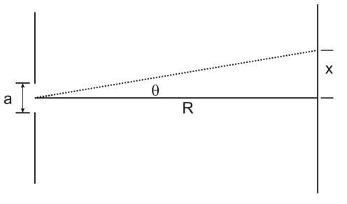
Diffraction leads to a fundamental, defining formula for the limitation in angular (spatial) resolution for any remote sensing system: the Rayleigh criterion. The Rayleigh criterion is traditionally presented in the one-dimensional (1D) case, where an infinite single slit is considered. This is illustrated in Fig. 3.20.
The somewhat out-of-scale figure shows light rays incident on a slit. For purely geometrical optics, there would be a white spot on the surface below, corresponding to the size of the slit. Instead, there is a central maximum with a width determined by the wavelength of the light, the width of the slit, and the distance from the slit to the surface below, or range.
The intensity goes as:
a is the width the of the slit, x is the distance along the target surface away from the center line, R is the range, and![]() is the wavelength.
is the wavelength.
The function in brackets is the familiar sinc function, which has magnitude one at ![]() then drops to zero at
then drops to zero at![]() This occurs when:
This occurs when:
The width of the central maximum is just twice this value, and we get a well-known result: that the angular width of the first bright region is![]()
![]() Note that the secondary maxima outside this region can be important, particularly in the radar and communications worlds—these are the side lobes in the antenna pattern of a rectangular antenna.
Note that the secondary maxima outside this region can be important, particularly in the radar and communications worlds—these are the side lobes in the antenna pattern of a rectangular antenna.
What does this have to do with optical systems? The concept means that for a finite aperture, there is a fundamental limit to the angular resolution, which is defined by the ratio of the wavelength to the aperture width or diameter.
Figure 3.20 Single slit diffraction pattern.
Figure 3.21 Single slit diagram for the geometry of the diffraction pattern.
The formula applies exactly to rectangular apertures, as will be seen in the radar section:
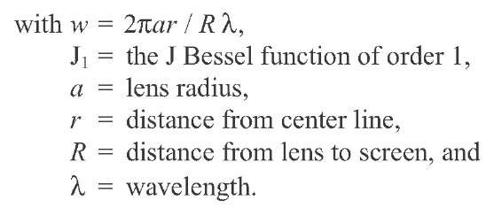
where![]() is the angular resolution, and D is the aperture width. This formula needs to be modified for circular apertures. The result is effectively obtained by taking the Fourier transform of the aperture shape, which for a circular aperture results in a formula involving Bessel functions:
is the angular resolution, and D is the aperture width. This formula needs to be modified for circular apertures. The result is effectively obtained by taking the Fourier transform of the aperture shape, which for a circular aperture results in a formula involving Bessel functions:
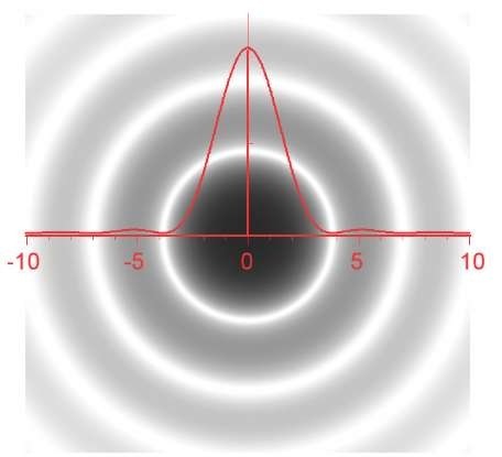
This function is illustrated in Fig. 3.22. The first zero occurs where w = 3.832, which leads to a relatively famous result, that the radius of the![]() x distance/lens radius, or that the angular resolution of a lens is:
x distance/lens radius, or that the angular resolution of a lens is:
Figure 3.22 Airy pattern for diffraction from a circular aperture.
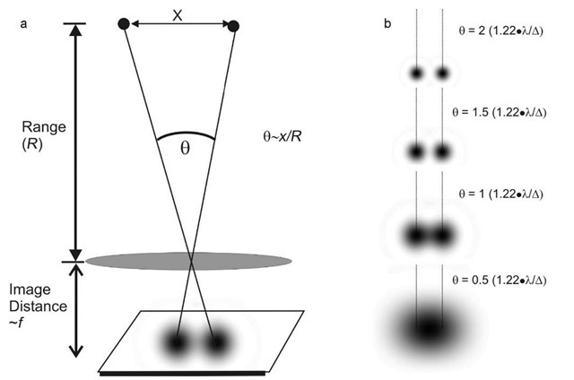
So what are the implications? As angular resolution improves, two adjacent objects become separable, as illustrated in Fig. 3.23. The concept is generally best understood in astronomical applications, where A0 is the angular separation between two stars. In the figure, it can be seen that the two stars can just be distinguished when their angular separation is A0, as defined in Eq. 3.7. The concept extends directly into terrestrial applications, however, and defines the ground separation distance (GSD), which is the product of A0 and the range from sensor to target.
Note that there are again secondary maxima outside the main beam, which again would be sidelobes for a circular antenna.
Application: Consider a Hubble-like system orbiting at an altitude of 200 nautical miles, or 370 km, and assume it is nadir-viewing, so that the range is just the altitude.
Figure 3.23 (a) Two objects (stars) separated by a distance x just corresponding to the Rayleigh Criteria for a cylindrical optic. (b) Here are two point targets at a range of 400 km. The objects are separated by 10 m, so the angular separation is ~25 ^rad. The wavelength is 0.5 ^.m. The four images shown here illustrate what happens as the diameter of the optic (mirror or lens) varies over the range: 12.2, 24.4, 36.6, and 48.8 mm. The second image from the bottom matches the Rayleigh criterion—the objects are separated by![]()
![]() and can just barely be distinguished. The two at top are separated by twice
and can just barely be distinguished. The two at top are separated by twice![]()


