7.10.
Tests for checking the rotation of a body are made for three conditions :
(a) Run-out. (b) Periodical axial slip, (c) Camming.
We shall now study the definition and meaning of these three conditions and then the
ways to measure these.
7.10.1.
Run-out.
A round body can be said to be running true on its axis when a dial
indicator with its feeler placed against the surface of the round body does not show any
variation in reading. Run-out is caused when there is some deviation in the trajectories of
points on a section of the surface is relation to the axis of rotation (errors of position) and the
movement of the axis of rotation if bearing surfaces or bores are not exactly circular (errors of
bearings). In other words, run-out is the resultant of the radial throw of the axis, of the out of
roundness of the component, and of the errors of bearings.
Out of round is the error relative to the circular form of a component in a plane
perpendicular to the axis at a given point of the latter. Its definition and the method of
measurement have already been discussed in details. However, it may be again reminded that
the value of out of round for a shaft is given by the difference between the diameter of the
inscribed circle and the smallest measurable diameter of the shaft; and for a hole, it is given
by the difference between the diameter of the inscribed circle and the largest measurable
diameter of the hole, each of them measured in a plane perpendicular to the axis.
Radial throw of an axis at a given point is the
distance between the intersection of the geometrical axis
and the rotating axis with a plane perpendicular to the axis
of rotation at a given point (Fig. 7.54).
The geometrical and the rotating axes may be paral-
lel to each other or inclined. They will be parallel if the
radial throw is constant at any point of the axis. From the
metrological point of view, the two axes are considered to
be identical when the error of rotation of the cylindrical
surface, at each measuring point, does not exceed the
specified value.
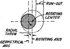
Fig. 7.54. Radial throw of an axis.
Run-out (or out-of true running) of an exactly round component in a given section will
wice the radial throw of the axis in a given section.
7.10.1.1.
Measurement of run-out.
This is tested, for the external surface, bv arrang-
ing the plunger of the dial gauge normal •
to the revolving surface and the readings
of the dial noted as the spindle is slowly
rotated by 360°, and for the internal sur-
face by bringing the plunger into contact
with mandrel fitted in the bore. The test-
ing is usually carried out in both vertical
as well horizontal planes.
It is essential for this test that the
spindle be rotated sufficiently before
starting the test, in order to ensure that
the lubrication film will not vary during
the test and that the temperature at-
tained may be considered as the normal
running temperature of the machine.
Further it may be noted that this test
takes into account onlv errors in the bear-
ings of spindle and does not give any information of the exact shape of the cylindrical or conical
bore, or of actual position of the bore in relation to the axis of rotation.
On the external conical surface, the feeler of the dial gauge should be set at right angles
to the generation line. It may be noted that in this case if there is only axial movement in the
spindle during its rotation then the diameter of the circle being checked will vary and as a
result the run-out will appear greater than the actual. For this reason either the axial slip
should be measured before hand and its effect on the measurement of run-out computed
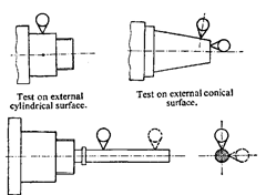
Fig. 7.55. Test on internal surface.
according to the angle of taper or else this test be applied only to tapered components having
very small taper.
While performing this test on the internal surface with the help of mandrel, the following
points should be remembered :
(i) Checking should be done at two sections, one near the housing and other at a specified
distance apart. (This is necessary to check that the axis of the mandrel might not have crossed
the axis of rotation in the plane of measurement).
{ii) Above checking to be repeated 4 items and average taken, by turning the mandrel,
through 90° in relation to the spindle every time. (This test checks for any lack of accuracy in
inserting the mandrel into the bore).
However, it may be noted that the testing of internal surface with test mandrel does not
check the exact shape of the bore.
7.10.2.
Periodical Axial Slip.
Before we consider the definition and measurement of
periodical axial slip, let us understand the meaning of minimum axial play. When a part rotates
and if some axial movement (measured at rest at each of the several positions around the axis)
along its axis is observed, it is known as axial play. And rotating part can be considered as
fixed in its axial direction, when its axial slip remains within the tolerance zone. The minimum
permissible axial slip defines the limit of the axial slip of the spindle during one slow rotation
with a slight axial pressure.
Periodical axial slip represents the extent of reciprocating motion of a rotating
component along its axis of rotation, when the influence of the minimum axial play is
eliminated by applying axial pressure in a given direction.
The value of the axial slip is determined by apply-
ing a force along the axis of rotation and arranging the
feeler of the dial gauge to touch the rotating surface a
small distance away from the axis of rotation as shown
in Fig. 7.56. Test is made for each of the two positions at
180° of the dial gauge and the algebraic mean of the
readings taken. When testing the thrust bearing of the
ball or roller type, the test should be made through at
least two revolutions.
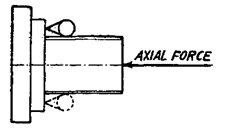
Fig. 7.56. Axial slip determination.
Periodical axial slip is determined by applying a slight pressure to the spindle in the
lirection of measurement and arranging the feeler of dial gauge along the centre of the front
ace, as far as possible along the axis of rotation. Thus it is essential that such a device be used
vhich permits a force to be applied along the axis and at the same time permits a dial gauge
o be placed on the same axis. For this purpose a dynamometer is used which applies force in
he centre of spindle through its surface and also has opening in the middle for the dial gauge
o be accommodated. In the case of a lead screw, the axial force is applied by movement of the
slide when the nut is connected.

Fig. 7.57. Determination of periodic axial slip.
If the spindle is hollow then a short mandrel, having a plane face perpendicular to the
axis may be used [Fig. 7.57 (a)]. If the spindle has a centre, a steel ball as shown in Fig. 7.57
(b) may be inserted. In this case the feeler of the dial gauge should have flat surface.
7.10.3.
Camming.
The following definitions apply to the camming of a plane surface
rotating around an axis :
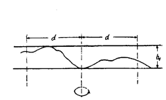
(a) Camming (when surface is not flat)
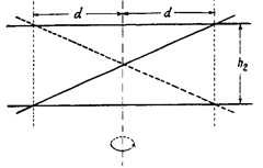
(b) Camming at a distance.
(a) Camming of a surface. Camming is the defect
of a plane surface which, when rotating around an axis,
does not remain in a plane perpendicular to this axis.
Camming is given by the distance h separating the two
planes perpendicular to the axis between which the
points of the surface are moving during the rotation.
(b) Camming of the surface at a distance from
the axis. This is represented by the distance h separating
two planes perpendicular to the axis between which
moves the portion of surface delineated by a revolving
cylinder, the diameter of which is 2d, and which has, as
its axis of symmetry, the theoretical axis of rotation of the
surface.
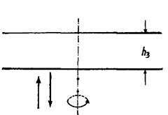
(c) Camming (with periodical
axial displacement).
Fig. 7.58
Camming is the resultant of various defects of the surface and axis of rotation (hi, h2,
h3 in Fig. 7.58), for example, surface not flat [Fig. 7.58 (a)], surface and axis of rotation not
perpendicular [Fig. 7.58 (b)], periodical axial displacement of the axis [Fig. 7.58 (c)].
[Note. When the plane concerned has a geometrical axis
(part A, Fig. 7.59) which does not coincide with the axis of
rotation, the resulting radial throw gives camming. This defect
is due to the lack of perpendicularity of the face to the axis of
rotation. In practice, the run-out does not have a great effect,
as it affects camming only in the ratio 1: 2. When the run-out
is constant on all points of the axis (eccentricity), there is no
camming.]
Thus in brief it could be said that camming relates to
rotating plates and is measured in relation to a plane perpen-
dicular to the rotating axis, and represents the deviation, at
any point, of all the trajectories of all the points on a given
circumference of the surface to be checked. It includes errors
of shape of the face, the angle of the latter in relation to the
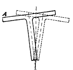
Fig. 7.59. Camming given by
radial throw.
axis of rotation, the radial throw and the periodical axial slip of the spindle. It may be noted
that this does not include the minimum axial play of the rotating component.
The object of checking camming is to verify that all the points in the same circle on the
front face are in the same plane perpendicular to the axis of rotation and that the axial position
of this plane does not vary during the rotation of the spindle. Testing is always done on the
points farthest from the axis on the circumference, because the camming increases for the
points away from the axis of rotation. In order to analyse the origin of camming, the defects of
the surface and of the axis should be measured separately. The axial slip should be measured
in every event for measuring camming.
The testing is carried out by arranging the feeler of the dial gauge at a given distance
L from the centre and at right angles to the face. Readings are taken by placing the plunger
successively at a series of points spaced around the periphery (Fig. 7.59). The spindle is rotated
continuously at slow speed and given a slight end pressure to eliminate the effect of play in
the thrust bearings. The deviations between the maximum and minimum readings are noted
for each position of the dial and the greatest deviation represents the camming.
