7,9.
7.9.1.
Introduction.
In the assembly of circular parts, only the dimensional tolerances
on diameter will not suffice the requirements, but it is the geometrical accuracy (accuracy of
form) that needs closer attention. If cylindrical parts are measured from devices having
diametrically opposite contacts such as micrometer etc., though they may be found to be within
the dimensional tolerances and still may not be perfectly circular, which would be noticed
during the assembly of parts. (Refer Fig. 7.26). Thus the method of circularity measurement
has to be such which detects the various possible errors of circularity and this is always done
by rotating a part and not measuring static diameter alone.

Fig. 7.26. Errors in circularity.
7.9.2.
Sources of Out-of-Roundness.
Several reasons when machining parts can be
attributed to cause out-of-roundness. These are clamping distortion, spindle run-out, presence
of dirt and chips on clamping surfaces, imbalance, heat and vibration. The characteristic
roundness shape varies greatly depending on the method of generation.
The tolerance on roundness is critical and it should be much closer (usually five times)
than that of the other dimensional tolerance which it effects.
7.9.3.
Different types of Irregularities of a Circular Part.
The errors of circularity
at a cross-section can be of the following nature :
(i) Ovality (There is some difference between the major and minor axes.) [Refer
Fig. 7.27].
(ii) Lobing (In this case the diameters at any two opposite points are constant, but still
it is not circular form). [Refer Fig. 7.28]
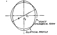
Fig. 7.27. Ovality, i.e. DX*D2* D.
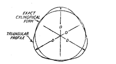
Fig. 7.28. Lobing : Diameters at places equal, but
still not circular form.
(iii) Irregularities of no specific form. (Fig. 7.29)
7.9.4.
Causes of out-of-roundness.
Out-of-
roundness of machined parts could be due to poor
bearings in the lathe or grinding wheel spindle, or to
deflections of the workpiece as the tool is brought to
bear on it. Shafts, ground between centres can be
out-of-round due to poor alignment of the centre or
deflection of the shaft.
Lobing is particularly difficult to avoid in many
machining processes. A round bar or ring-type part
held in a 3-or-5-jaw chuk is compressed at the points
of contact. Even if the part is turned or ground perfect-
ly circular on the machine, when it is removed from the
chuck the stress in the metal will be relieved, causing
three or five lobes.
7.9.5.
Definition.
The error of circularity is defined as the radial distance between the
minimum circumscribing circle and the maximum inscribing circle, which contain the profile
of the surface at a section perpendicular to the axis of rotation.
Polar graph (a graphical record, suitably magnified, of the displacement of the stylus of
measuring elements, as either the stylus or the part rotates on the axis of the precision spindle)
is interpreted by using concept of reference circle or a pair of circles which can be
drawn/recorded or otherwise superimposed on the graph. The position of the reference circle
and its centre is not arbitrary but is chosen to fulfil certain conditions.
Obviously, it is possible to draw a large number of circles for a given profile and infer
different results. Accordingly four types of reference circles as described below have been
standardised and the results should be specified indicating the reference circle adopted. Only
in this can an unambiguous and repeatable value for the out-of-roundness of any particular
profile be obtained.
7.9.6.
Reference Circles.
The four reference circles used in measurement of roundness
are:
(i) Least squares circle. This circle represents the average of all the peaks and valleys,
and can be defined mathematically as follows :
“The sum of the squares of a sufficient number of equally spaced radial ordinates,
measured from the circle to the profile has minimum value”. The centre of such a circle is
referred to as the Least Squares Centre (L.S.C.). Out of roundness is defined as the radial
distance of the maximum peak from this circle (P) plus the distance of the maximum valley
from this circle (V) i.e. P + V.
It is very easy to calculate the position of the least squares circle by computer but very
difficult by manual methods :
(ii) Minimum zone or minimum radial separation circles. These are two concentric
circles that just enclose the profile and which have minimum radial separation. The value of
the out-of-roundness is the radial distance between the two circles. The centre of such a circle
is termed as the minimum zone centre. These circles can be found by using a template, or
computed by necessary accessories.
(iii) Maximum inscribed circle. This is the largest circle that can be drawn inside the
profile without cutting it. Its centre and radius can be found by trial-and-error using
compasses, by template or computer. The out of roundness is specified as the height of the
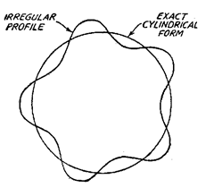
Fig. 7.29. Irregularities of no specific form.
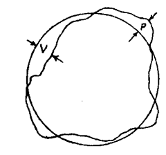
Fig. 7.30. Least Squares
Reference Centre.
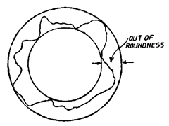
Fig. 7.31. Minimum radial
separation circles.
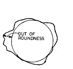
Fig. 7.32. Maximum inscribed
circle.
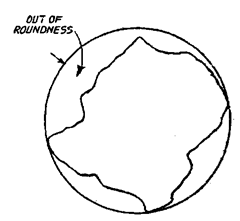
Fig. 7.33. Minimum circumscribed circle.
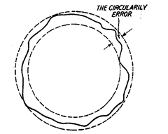
Fig. 7.34. Trace produced by a polar recording instrument.
largest peak above the circle. This value is nearly equivalent to P + V, since V is zero, there
being no valleys inside the circle.
(iv)
Minimum circumscribed circle. This is the smallest circle that will completely enclose
the profile without cutting it. Its centre and radius can be found in a similar manner to that
of the inscribed circle. This out-of-roundness is the distance of the lowest valley fromthe circle,
which is also equivalent to P + V, since P is zero, there being no peak outside the circle.
A template for rapid manual assessment of the graph is supplied with most instruments.
It consists of some transparent material on which is engraved or printed a series of concentric
circles matching the circular ordinates of the chart. To use it, the chart is placed under the
template and then moved about to determine the position of reference circles. It can be used
to find the circumscribed or inscribed reference circles and the minimum zone circles.
Error of circularity is determined by the modern circularity measuring instruments
which make use of precise spindle on which the indicating means are carried and in which
turn tables are provided for carrying the work. The radial variations discovered by the
instruments are generally displayed in the form of a polar profile graph or a meter reading or
both. From the polar graph, the departures from the ideal circle can be determined as “the
difference in radius between two best fitting concentric circles, within which the profile is just
contained.” The radial distance between the minimum circumscribing circle and the maximum
inscribing circle is the measure of the error of circularity.
In Fig. 7.34, is shown a trace produced by a polar recording instrument which is actually
an amplified record of the displacement of the stylus of the measuring instrument. The
procedure for making numerical assessment of the circularity error of this trace is to draw
concentric circles on the polar graph which pass through the maximum and minimum points
in such a way that the radial distance of the minimum circumscribing circle containing the
trace or the maximum inscribing circle which can be fitted into the trace is minimum. In other
words, many concentric circles touching maximum and minimum points respectively are
drawn by hit and trial and the one set in which the radial distance between the outer and inner
circles is minimum is considered for determining the error of circularity. This could also be
interpreted as the smallest ideally, circular ring gauge that can be passed over the workpiece
or the largest ideally circular plug gauge that can be passed through the work-piece. The error,
of course, can be expressed w.r.t. any of the four reference circles illustrated above.
7.9.7.
Roundness and circularity.
Often the terms roundness and circularity are used
interchangeability. Roundness is defined as a condition of a surface of revolution (like cylinder,
cone or sphere) where all points of the surface intersected by any plane perpendicular to a
common axis in case of cylinder and cone (or passing through a common centre in case of sphere)
are equidistant from the axis (or centre). Since the axis and centre do not exist physically,
measurements have to be made with reference to surfaces of the figures of revolution only.
Whatever is measured by referring to the surface of revolution is the circular contour. It may
be understood that while roundness expresses a particular geometric form of a body of
revolution in all the three dimensions, the circular contour is the characteristic form of the
entire periphery of a plane figure. For measuring roundness, it is only the circularity of the
contour which is determined.
7.9.8.
Devices for measurement of roundness.
The most commonly used devices for
measurement of roundness are :
(1) Diametral. (2) Circumferential confining gauge—a shaft is confined in a ring gauge
and rotated against a set indicator probe. (3) Rotating on centres. (4) V-Block.
Piece rotating against a set probe (a) of fixed angle, (b) of adjustable angle.
(5) Three-point probe (120° spacing).
(6) Accurate spindle.
(a) part fixed, exterior spindle with probe rotates, (b) probe fixed, part rotates with
spindle.
7.9.8.1.
Diametral Method.
In this method, the measuring plungers are located 180°
apart and the diameter is measured at several places. This method is suitable only when the
specimen is elliptical or has an even number of lobes. Diametral check does not necessarily
disclose effective size or roundness. This method is unreliable in determining roundness.
7.9.8.2.
Circumferential Confin-ing Gauge. Fig. 7.35 shows the principle of this method.
It is useful for inspection of
roundness in production. However, this
method requires a separate highly ac-
curate master for each size part to be
measured. The clearance between part
and gauge is critical to reliability. This
technique does not allow for the measure-
ment of other related geometric charac-
teristics, such as concentricity, flatness of
shoulders, etc. The values obtained are
dependent on the shape of the specimen.
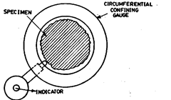
Fig. 7.35. Circumferential confining gauge.
7.9.8.3.
Rotating on centres. (Refer Fig. 7.36).
Some parts, (such as shafts) may be
inspected for roundness while mounted on centres. In
this case, reliability is dependent on many factors like
angles of centres, alignment of centres, roundness
and surface condition of the centres and centre holes,
and runout of piece. Out-of-straightness of the part
will cause a doubling runout effect and appear to be
roundness error.
Any or all of these factors may combine, creat-
ing a high degree of uncertainty as to exact nature of
the error.
For workshop purpose, the V-block method is quite accurate as it is capable of indicating
normal requirements of accuracy. However for very precise job where more reliable and more
accurate results are desired, the second method is recommended which is quicker and also
eliminates the effects of angle of the block and the number of lobes on part, but of course, is a
very costly one.
7.9.8.4.
Assessment using a V-block.
The set up employed for assessing the circularity
error (lobing) by using a V-block is shown in-Fig. 7.37, i.e., the vee-block is placed on a surface
plate and the work to be check-
ed is placed upon it. A sensi-
tive dial indicator is firmly
fixed in a stand and its feeler
made to rest against the sur-
face of the work. The work is
rotated to measure the rise
and fall of the work-piece. For
determining the number of
lobes on the work-piece, the
work-piece is first tested in a
60° V-block and then in a 90°
V-block. The number of lobes
is then equal to the number of
times the indicator pointer
deflects during rotation of the
workpiece through 360°. The idea of testing the work-piece in two V-blocks is that when an
elliptically shaped part is rotated on a V-block is that when an elliptically shaped part is rotated
on a V-block of angle 60°, no change in reading is indicated, whereas if the same part is rotated
on a 90° angle Vee-block, two maximum and two minimum readings are indicated on the
indicator.
The method of determination of the circularity error by V-block has certain limitations
and, therefore, the following points should be born in mind.
(a) The error of circularity measured on a V-block is greatly affected by the following
factors :
(i) Angle of V-block very much influences in the determination of circularity error, i.e.
if the circularity error is say Ae, then it is possible that the indicator shows no variation, or
same as Ae, or twice Ae, or thrice Ae, or some other value for each position of the instrument
when V-blocks of different angles are used. This is because of the fact that as the angle of V
changes the place where the work-piece rests also changes. Ultimately it will be noted that the
same work-piece rests at higher place in V-Block of smaller angle and at lower place in V-block
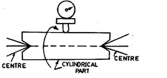
Fig. 7.36. Inspecting shaft for roundness.
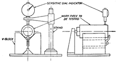
Fig. 7.37. Assessing circularity using a V-block.
of larger angle and thus the indicator will show different readings for same work-piece kept
in same position on different angle V-blocks.
(ii) Position of the instrument, i.e. whether measured from top or bottom.
(iii) Number of lobes on the rotating part (e.g., elliptical, triangular, quadrilateral,
pentagonal etc.)
(b) The instrument’s position should be in the same vertical plane as the point of contact
of the part with the V-block. If the error is measured at a point far from the V-block, the error
of circularity will be influenced by the radial run out of the part.
(c) A leaf spring should always be kept below the indicator plunger and the surface of
the part, otherwise readings are likely to be affected by minute undulations of the surface,
such as surface roughness.
It is obvious that with different angle of V-blocks, dial indicator shows different readings
for the same work-piece placed in the same position. If this problem is studied further by
analysing an elliptical workpiece on different angle V-blocks, it will be found that some solution
can be arrived at. Let us consider an elliptical work-piece whose major axis is 2A more than
the minor axis as shown in Fig. 7.38.
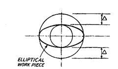
Fig. 7.38. Major axis 2A more than minor axis.
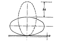
Fig. 7.39. 2A error revealed when elliptical object is
placed on flat surface.
We will place this work-piece on different angle V-blocks first with major axis placed
along the direction of dial movement and then with minor axis along the direction of
dial-movement. This is so because the work-piece has two number of lobes.
It may be noted that it is possible to take dial readings both from top as well as bottom.
Consider the case when work-piece is placed at flat
surface in two positions as shown in Fig. 7.39. It will
be noted that the error of circularity when measured
from top = 2A and when measured from bottom = 0,
whereas the actual error of circularity in the work-
piece = A.
Similarly, if the work-piece is placed on a
V-block of angle 120°, it will be found by calculation
or otherwise that the error of circularity in this case
when measured from top = 1.58A, whereas if
measured from bottom = 0.42 A.
In the same way, it will be found that when
work-piece is tested on the 108° V-block, the cir-
cularity error measurement when measured from
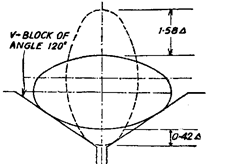
Fig. 7.40. Elliptical workpiece tested on
V-block of 120°.
top = 1.38A and 0.62A if measured from bottom. The corresponding values for 90° and 60°
V-block will be A, A and 0, 2A respectively.
Thus for an elliptical work-piece which has got 2 number of lobes, the ratio of circularity
error measurement by dial indicator on different V-blocks and the actual error is as given
below :
| Angle of V-block | Measurement from top | Measurement from bottom |
| 60° | 0.00 | 2.00 |
| 90° | 1.00 | 1.00 |
| 108° | 1.38 | 0.62 |
| 120″ | 1.58 | 0.42 |
![]()
can be determined for different shapes of work-pieces, i.e. having different number of lobes.
7.9.8.5.
V-Block.
(a) Fixed Angle. Depending on the number of lobes on a part, the
following angles of V-blocks are recommended for measurement of correct roundness by
V-block method.
| Lobes | Angle of V-block |
| Three-point out of roundness | 60° |
| Five-Iobed part | 108° |
| Seven-lobed part | 128° 34′ |
(b) Adjustable V-Block. It is usually difficult to ascertain the number of lobes of a part
and have large number of fixed angle V- blocks. V-block which can be adjusted to correct angle
to show out-of-roundness is better choice.
V-Block method is limited in the determination of roundness of parts because it is
suitable only when the number of lobes is known and is uniformly arranged, which is never
the case.
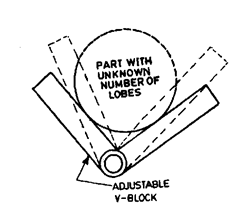
Fig. 7.41. Adjustable V-block.
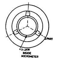
Fie. 7.42. Three point probe.
7.9.8.6.
Three-Point Probe. (Refer Fig. 7.42).
The three-probe with 120° spacing is
very useful for determining effective size in cases of doubtful geometry of part. They perform
like a 60° V-block. Like 60° V-block, it will show no error for 5 and 7 lobes, magnify the error
for 3-lobed parts, show partial error for randomly spaced lobes.
7.9.8.7.
Accurate spindle.
None of
the five methods discussed above are satis-
factory for measuring roundness absolute-
ly. Accurate spindle method is a method to
provide a definitive value for calibration of
roundness. There are innumerable types of
spindle designs available for generation
and inspection of round shapes. Various
designs are : ball bearings, roller bearings,
plain ball spindles, plain bearings (journal
type), metered oil flow and fluid-bearing
(gas bearing and oil-bearing). These
spindles are available in a wide range of
tolerances (down to a fraction of a micron).
7.9.8.8.
Spin TableIt is a highly precise spindle.
It is a rotating table-type of spindle,
useful for generating cylindrical, conical and spherical shapes when mounted on the jig grinder.
It is designed for the^ generation of essentially round shapes. When the spin table is mounted
on the Micro-Sine Table, tapers and conical shapes are ground and to an exact included angle.
If the spin table is placed on the jig grinder so that its spindle is horizontal, either by mounting
it on an angle iron or on the Sine Table.
The conventional design for this type of spindle includes the use of balls. For maximum
rigidity and for minimising the danger of brivelling, the Spin Table instead uses precision
rollers under stiff radial and axial preload. Trueness of rotation of the Spin Table is held to
0.0001 mm (Total Indicator Reading) and 0.0005 mm maximum axial deviation, including the
effects of camming, flatness and parallelism. In rotation, these accurate spindles describe a
perfect circle to which the part may be compared at all its radial ordinates.
Out-of-roundness is shown by the movement of high-magnification comparators. It often
suffices to merely observe and note indicator readings. These are usually equipped with means
of recording the (linear or polar) results. The polar recorder is an auxiliary device having
several rotational speeds, synchronous to those of the measuring spindle. Deviations from true
roundness registering on an indicator are traced on circular graph paper at magnifications
upto 20,000 to provide a permanent physical record. By overlaying a special transparent
template where there are concentric circles representing calibrated value (such as 1 line
= 0.00025 mm) to the graph, deviations from roundness may be easily understood and analysed.
This can be accomplished even without exact alignment of the part with the spindle.
7.9.9.
Roundness Measurement by Plotting Polar Graph.
The idea of the actual
shape of the work-piece can be had by actually plotting the polar graph, which is explained
later. Once the shape is known, the value of the constant can be noted from the table given on
next page corresponding to that very shape and the actual error of circularity determined.
The procedure to be adopted for the measurement and drawing of the polar graph and
therefrom the error of circularity is given below :
First of all 12 markings equally space at angles of 30° are made on the face of the
work-piece to be measured. The work-piece after properly cleaning is then placed on the V-block
against a rigid block with a steel ball in between as shown in Fig. 7.37. The dial indicator is
placed just above the work-piece so that it is touching the work-piece nearly at the centre of
the V-block. The work-piece is then rotated such that the marking on the work-piece is below
the indicator plunger. A small strip (leaf spring) is fixed between the indicator plunger and
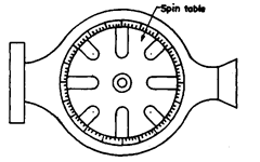
Fig. 7.43. Accurate spindle.
the surface of the part. The readings of the dial
indicator are noted down for all the markings. This
is repeated three times to take the average value.
For plotting the polar graph, a suitable scale
is chosen depending on the maximum value of the
reading. Then a circle of diameter nearly 4 times the
maximum reading of the dial indicator is drawn and
is divided into 12 number of angular divisions as
shown in Fig. 7.44. Inside the outer circle, another
concentric circle of suitable diameter is drawn. Ac-
tually there are standard diameters drawn on polar
graphs. Then the values of the indicator are plotted
in radial direction taking the smaller circle as the
reference circle in order that both the positive and
negative readings are plotted within the prepared
graph.
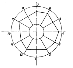
Fig. 7.44. Measuring roundness by
plotting polar graph.
| Table for determining the value of K different shapes of work-pieces | ||||||||
| Shape of the Work-piece Elliptical |
Angle of vee-block | |||||||
| 60° | 90° | 108° | 120° | |||||
| Measure- ment made from top |
Measure- ment made from bottom |
Measure- ment made from top |
Measure- ment made from bottom |
Measure- ment made from top |
Measure- ment made from bottom |
Measure- ment made from top |
Measure- ment made from bottom |
|
| 0.00* | 2.00 | 1.00 | 1.00 | 1.38 | 0.62* | 1.58 | 0.42 | |
| Equilateral Triangle | 3.02 | 3.02 | 2.05 | 2.05 | 1.44 | 1.44 | 1.00 | 1.00 |
| Quadrilateral | 0.10* | 2.00 | 0.415 | 2.40 | 1.01* | 2.01 | 0.38 | 1.00 |
| Pentagonal | 0.5* | 0.5* | 2.07 | 2.07 | 2.24 | 2.24 | 2.03 | 2.03 |
| Hexagonal | 3.00 | 1.00 | 1.00 | 1.00 | 0.08* | 2.00 | 0.16* | 2.11 |
| Heptagonal | 0.10* | 1.10* | 0.02* | 0.02* | 1.40 | 1.40 | 2.04 | 2.04 |
*Out of experience it has been found out that the angles of vee-blocks corresponding to values of K
indicated with aesterisk mark should not be used.
Individual points are then joined by straight lines, thus obtaining the actual profile of
the measured work-piece. The error is measured as the radial distance between the minimum
circumscribing circle and the maximum inscribing circle for the profile obtained. This is done
by hit and trial method such that this distance is mimmum.
The actual value of error of circularity is given by,
![]()
where K is a constant, value of which depends upon shape of work-piece and angle of V-block.
7.9.10.
Roundness Measuring Spindles.
Roundness measuring spindles are of two
kinds :
(i) Overhead spindle in which the part is fixed on a staging platform and the overhead
spindle carrying the comparator rotates separately from the part (Refer Fig. 7.45).
It can determine roundness as well as camming (circular flatness). The concentricity
can be checked by extending the indicator from the spindle and thus the range of this check is
limited. Flatness and squareness can be inspected by physically sliding the workpiece past the
indicator as is done on a surface plate. Height of the work-piece is limited by the location of
overhead spindle.
Since the workpiece is stationary and separate from the spindle, the spindle is not
affected by load of workpiece.
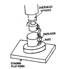
Fig. 7.45. Roundness measuring spindle-
overhead spindle.
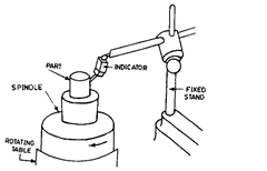
Fig. 7.46. Roundness measuring spindle-
rotating table.
(ii) Rotating table—in which the spindle is integral with the table and rotates alongwith
it. The part is placed over the spindle and rotates past a fixed comparator (Refer Fig. 7.46). It
can determine more geometric characteristics without having to move the part.
The rotating table spindle can measure roundness, concentricity and camming (circular
flatness). This design allows the inspection of concentricity over a great range along the part
axis. Squareness inspection requires slidingthe indicator and stand, or an auxiliary horizontal
movement. The height of workpiece is no limitation. However, weight of workpiece may result
in inaccuracy since it has to be supported on the rotating spindle. Spindle accuracy may be
deteriorated due to eccentrically mounted load. There is also the danger of damaging the
spindle during mounting of workpiece. With small parts such as bearings, ring gauges etc. no
loss of accuracy may be there.
7.9.10.1.
Measurement of camming,flatness and squareness
. The overhead spindle
can inspect camming. The inspection of square-
ness, taper and flatness is accomplished only by
sliding the workpiece, which is not a good prac-
tice.
The rotating table can also inspect cam-
ming but squareness, taper and overall flatness
are inspected by sliding indicator and stand,
which is not good practice.
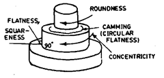
Fig. 7.47. Measuring camming, flatness,
squareness, etc.
7.9.11.
Features of Universal Measuring Machine Spindle.
It is absolutely essen-
tial that any measuring machine employed for accurate hole location be fitted with a spindle
that rotates true. The locating process is dependent on the use of an accurate spindle. If the
spindle does not have a constant axis of rotation, it can not give correct readings for distance
between two holes. Further, if the spindle does not rotate true, again it can’t give actual
centre-distance of two holes. If two holes to be measured are out-of-round, a true spindle will
most accurately determine the correct centre line of the hole. Since Universal Measuring
Machine measures hole location to less than one micron, its spindle must be accurate to a
fraction of a micron.
Accuracy of a Universal Measuring Machine Spindle can be verified by comparison to
a master glass hemisphere, (the latter’s being around .025 micron) or a master round hole. A
polar recording is made as the spindle is compared to the master. Accuracy of the hemisphere
or master hole is self accuracy proved by turning it 90° and making a second polar chart. If
this is not perfect, its error is shown displaced 90° on the second polar trace.
Spindle and Quill. The two main elements of Universal Measuring Machine are the
spindle shaft and the quill. The tolerance of these parts as to size, straightness, and roundness
is to a fraction of a micron. This accuracy is achieved by random motion of handlapping process.
Between the spindle shaft and the quill inside are four hardened 3 mm diameter balls held in
a brass retainer. To establish the correct preload, the size of the balls must be determined
precisely. Uniformity of ball size is also prerequisite to rotational accuracy of the spindle.
Balls of 3 mm diameter are used as a thrust between a collar on the spindle, and a
shoulder on the quill to enable spindle rotation free of axial camming.
The quill assembly slides vertically within the housing, guided by two lapped sleeves.
Clearance is held to 1.3 micron, allowing enough space for oil film thickness.
Yoke. Yoke assembly is meant to elevate/lower the spindle. Spindle is elevated/lowered
by a pinion which works against a rack set into the quill itself. The quill and yoke design must
make it possible to attain a vertical quill movement which is straight, aligned with the spindle
housing travel, and square to the table top.
Rotation of the Spindle. The spindle is rotated by hand through a knurled knob at
the top of the spindle for normal measuring application like locating hole or exploring the
geometry of a hole. When measuring roundness, the spindle is rotated at the rates or 1/2,1, 2
or 4 revolutions per minute by power.
Spindle Housing Travel. The spindle housing is elevated/lowered by a large hand-
wheel at the right of the column. It is primarily meant to accommodate larger workpieces. Its
travel is accurate and straight.
Polar Recorder. It is fastened to the right of the machine. It has its rotational speed
synchronous to that of spindle. It produces a permanent graphic record of roundness or other
features of a part, such as concentricity, squareness and taper.
7.9.11.1.
Characteristics that can be inspected by a Universal Measuring Machine.
The following characteristics can be conveniently measured by a Universal Measur-
ing Machine :
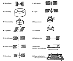
Fig. 7.48. Characteristics measureable by universal measuring machine.
All the above measurements are possible due to highly accurate spindle rotation, and
all movement of quill and housing being straight and parallel and also mutually square to the
table top and to the plane of travel of the base slideways.
7.9.12.
Measurement of error of circularity by modern precision machine.
In
the precision measuring machine intended for this purpose, the effects of angles of V-block,
the position of indicator and the shape of work-piece, i.e. the number of lobes are completely
eliminated.
In this instrument, a truly running spindle mounted on the high precision ball bearings
and carrying a micron indicator is employed. The accuracy of running of the spindle is of the
order of 1 micron. The spindle is mounted vertically on a right stand and the workpiece is
mounted on a co-ordinating table placed just below the spindle. The job is centered by means
of the co-ordinating table such that the axis of the spindle coincides with the axis of the job.
The remaining procedure for plotting the polar graph is same as with V-block, i.e. the 12
markings are made on the job and the spindle is slowly rotated starting from zero position and
noting the indicator reading for all the positions.
In the very high precision measuring instrument such as Talyrond, which has high
spindle running accuracy of less than 0.1 micron, a record of the exact profile of the job is made
automatically and thus the waviness is also superimposed upon the profile of the job.
Modern roundness measuring instruments (machines) are designed to make the
numerical assessment of departures from ideal roundness from one of the following two
centres, viz., (i) determination from minimum zone centre, i.e. a centre for which the radial
difference has a minimum value; (ii) determination from the least squares centre, i.e. a centre
defined on a “least squares” basis (the sum of the squares of the errors is the minimum).
Most of the machines, employ air bearing (non-contact type bearing) for the rotating
tables to ensure high accuracy of rotation. The other advantages of air bearings are (i) non-
contact bearing prevents accuracy fall to be caused by wear, (ii) accuracy of rotation is not
alliviated even if slight shock due to e.g., striking of work-piece against the table, (Hi) no
temperature rise from long hours of use and no oiling or warming up is required, (iv) recording
diagram having high reproducibility can be obtained in comparison with instruments employ-
ing mechanical bearing.
For the maintenance of ac-
curacy of air bearing, fresh and
clean air free from dust and mois-
ture is very essential.
The workpiece to be tested is
set on the rotating table and the
gauge head is brought into contact
with the workpiece. Rotating the
workpiece, roundness is measured
and the gauged value is recorded on
the polar electric spark recorder
synchronised with rotating table.
The signal from the gauge head is
amplified and applied to a polar co-
ordinate recorder giving straight
radial ordinates. The range of mag-
nification extends from x 50 to x
10,000. The graph obtained shows
the amount by which the periphery
of the component being checked
departs from a truly circular form.
The sophisticated machines have the provision to check concentricity, roundness,
alignment, squareness, parallelism and flatness. Usually tilting table is provided which can
be used for alignment of the rotating shaft of air bearing to the work centre or for ensuring
rectangularity between them when the measurement of concentricity or flatness is desired.
The tilting can be easily set on the table. The table turns at constant speed of 4 RPM or 6 RPM
which is specified on the recording chart.
The measured profile chart of the surface examined is plotted on circular chart paper
printed with polar co-ordinates. (Refer Fig. 7.49) The departure from roundness can be
assessed either by determining the centre of the two concentric circles having a minimum
radial separation, within which the graph is contained, or by the “least squares” centre and
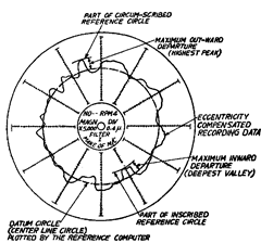
Fig. 7.49. Error of circularity measured in precision machines.
circle from which the undulations are measured. The first method can be employed by using
compasses or a transparent template with circular ordinates, under which the graph is floated
until a “best fit” is obtained.
(The more sophisticated machines have the provision of automatic eccentricity compen-
sation, which facilitates centering and assures distortion-free recording and makes judgement
of recorded results very easy.)
The second method involves computation and automatic plotting. The* andy ordinates
of the “least squares” centre for the reference circle are given by a meter reading on the
reference computer.
7.9.13.
Profile Filters.
When all of the radial deviations of a circular cross-section are
fully represented by a measured profile, the surface irregularities (of high frequency) can mask
the form of the profile or lobing or widely spaced undulations (low frequency). Depending on
the importance of requirements (whether low or high frequency irregularities), electronic
filters are incorporated in the electronic unit to clarify the profile trace for visual assessment.
Filters could either suppress the closely spaced undulations to reveal the form of the
profile more clearly, or suppress the widely spaced undulation and allow the magnifications
to be increased to reveal the closely spaced irregularities.
Electronic devices also compute the least square reference circle of the profile. The
analysis of departures from roundness can be speeded up by providing a visual display of
workpiece profile and any of the four reference circles. It also includes a digital display of
departures from the selected reference circles.
A single roundness graph is often of limited value because it can give only part of the
information needed to determine the overall functioning of a part. However, several related
roundness and straightness measurements can give a much more complete picture (like
concentricity, alignment, squareness, parallelism, straightness and conicity).
7.9.14.
Roundness Measuring Machines.
While it is easiest to generate a circular
cross-section and many objects we come across are circular, it is very difficult to check
roundness.
By definition, roundness is the property of a surface of revolution, where all points on
the surface are equidistant from the axis. Unfortunately this axis does not exist physically and
measurements can only be made by sensing the large number of points on the surface.
The out-of-roundness of any profile can be specified only when some centre is found from
which to make the measurements. Finding the centre from which to measure the variation in
profile is an important part of roundness measurement.
It is important to distinguish between diameter and roundness. Two are measured quite
differently and separately, by different methods, and instruments. While measurement of
diameter is done statically, for measuring roundness, rotation is always necessary. Diameter,
of course, is very much affected by out of roundness of a component. The simple measuring
method with a dial gauge and V-block suffers form the limitation that results may vary
according to the vee angle and spacing irregularities. It also gives a false impression when the
undulations are regularly spaced. This method, thus has its limitations and the possibility of
obtaining misleading results tends to offset the simplicity of the procedure. Modern engineer-
ing requires closer tolerances and more accurate measurement of roundness and tighter
control over the geometric form of round and cylindrical surfaces. Roundness measuring
instruments provide results of roundness measurements accurately, speedily and reliably
overcoming demerits of workshop methods. These instruments are of two types ; viz., the
rotating pick up type in which the workpiece is stationary and the pick up revolved around at;
and the turntable type in which the workpiece is rotated and pick up is stationary. In the
rotating pick up type instrument, precision spindle has to be designed to carry the compara-
tively light load of the pick up, which is easier to make. The weight of workpiece, being
stationary, is not a limitation on measuring capacity.
In the case of turntable, the more commonly used type, since the pick up is not associated
with the spindle, the instrument is more easily adapted to measurements associated with
roundness, such as concentricity and alignment. Reposition the pick up has no effects on the
reference axis. There is also more freedom in positioning the pick up to reach into slots or the
undersides of the shoulders without having to use long or cranked stylus arms. It is also
possible to measure straightness by providing straight vertical movement of the pick up, there
being no need of modifying the spindle or its mounting.
The pick up converts the minute movements of the stylus into electrical signal, which
is processed and amplified and fed to a polar recorder. A microcomputer is incorporated with
integral visual display unit and system is controlled from a compact keyboards, which increases
the system versatility, scope and speed of analysis.
Basically the final result is a roundness graph ; of course, it is not a magnified
cross-section of the part. Results may be displayed graphically on a CRT and the out-of-round-
ness and other values shown digitally as well. The graph plotted uses a radial magnification
of X2000 or so and the circumferential magnification is often less than one.
Usually several related roundness and straightness measurements are needed to give
a much more complete picture about the overall functioning of the part. Extensive analysis of
features like roundness, concentricity and cylindrically, can be done. System is programmed
to assess the roundness of workpieces with respect to any of the four internationally recognised
reference circles. A visual display of workpiece profile with the selected reference circle relative
to the axis of the instrument spindle can be obtained. Workpieces can be assessed over a full
circumference, and with undercut surface or an interrupted surface. With sufficient data the
appropriate reference circle can be fitted to the profile.

Measurement of roundness at different magnification levels.
Measurements can be made with respect to the spindle axis of the measuring instru-
ment, or with respect to an axis derived from the centre of selected measured plane on the
component. The program also provides functions like auto-centering, auto-ranging, auto-
calibration and concentricity. Figs. 7.50 to 7.53 show the effect on the graph of unequal
magnification of same component using 4 magnifications. This part has 5 lobed parts. At low
magnification the graph differs very slightly from a perfect circle. As magnification of radial
distance is increased, the effect becomes obvious.
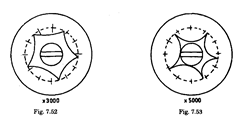
Effect of magnification on roundness measurement.
Microprocessors are used to assess out-of-roundness. The desired data for out-of-round-
ness is presented on C.R.T. without the need of analysing the polar graph by the operator.
7.9.15.
Modern Roundness Measuring Instruments.
The modern roundness
measuring instruments are based on use of microprocessor to provide measurements of
roundness quickly and in a simple way. There is no need of assessing out-of-roundness.
Machine can do centering automatically and calculate roundness and concentricity, straight-
ness and provide visual and digital displays. There are two basic types of roundness measuring
systems : (i) rotating worktable in which the workpiece rotates and the pick-up is stationary,
and (ii) rotating spindle, in which the workpiece is stationary and the pick-up rotates. The
bench top rotating worktable type of instrument is the most widely used in workshops and
inspection areas by virtue of its lower cost and versatility. It consists of a rotary table of around
200 mm diameter spindle pick-up mounting, vertical magnifiers having magnifications of order
of 100-10,000, and polar recorder. A computer is used to speed up calculations and provide the
standard reference circles (least squares circle, minimum zone circle and maximum inscribed
circle, and minimum circumscribed circle). Assessment of roundness can be done by templates.
Computer can provide the least squares circle superimposed on the profile graph, meter display
of the mean line average departure of the profile from the reference line, P, V and P + V, and
the x-y coordinates of the centre of the least square circle with respect to the axis of spindle
rotation (Please note that the out-of-roundness is defined as the radial distance of the
maximum peak (P) from the least square circle plus the distance of the maximum valley (V)
from the least square circle, i.e. (P + V). It is possible, by the machine, to record a reference
circle with the profile graph. Operator communication is via a small ke; jard which can be
held in hand. Instrument can be operated by untrained personnel. All the roundness analysis
functions can be performed with the addition of harmonic and slope analysis. Cylindricity
analysis can be done by collecting data from upto ten planes along a cylindrical component.
