6.5.
For studying various surface contours, optical flat is kept at certain inclination over the
surface to be tested. Normally daylight is used and spectrum of daylight has a wavelength of
approximately 0.0005 mm. Thus each fringe interval corresponds to a change in elevation of
the surface of 0.0025 mm. This clearly shows precision of the test. One more important point
to be kept in mind is that the contour of each fringe lies on points of equal height relative to
the surface of optical flat. Hence the fringe pattern as viewed through optical flat will represent
the contour map of the surface under test and spacing of fringes will represent height intervals
relative to the optical flat of X./2.
In the study of the surface contours it is important to know as to where the optical flat
is in contact with the surface being tested. The point or line of contact is usually where pressure
is applied causing the air film to be squeezed thin at that place. In mono-chromatic light, the
bands are sharper near the point of contact; and in daylight the point of contact can be seen
as the colour of the surface being tested.
LetXXbe the line of contact in Fig. 6.9. Contour BAB shows that all the points on it are
at equal height from the surface of the optical flat. Points A and C are at the centre of two
contours BAB and DCD. It is obvious in Fig. 6.9 that edge at B is X/2 higher or lower than C.
The air gap will keep on increasing as we move away from XX.
As BAB represents points at equal height, it means that B is
actually higher than C. This means that edges of this surface
are higher and central portion is lower, thus, it is concave
surface. Hence the general rule is that if the bands curve
around the point or line of contact, the surface is convex, and
if the bands curve in opposite direction, the surface is concave
(Fig. 6.10). The idea of the magnitude of convexity or concavity
can be had by the curvature of the bands. If the curvature of bands is more it indicates more
convexity and vice versa (Fig. 6.11).
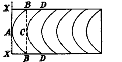
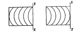
Concave surface Convex surface
Fig. 6.10
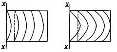
Less convex More convex
Fig. 6.11
Let us consider any surface having a scratch. The interference dark bands is that case
will be as shown in Fig. 6.10. Let D be the distance
between two fringes and d be the distance due to
Thus it is
![]()
possible to determine the depth of scratch also by this
method.
Fig. 6.13 shows two high or low spots, which can
be checked by pressure test, i.e. if by applying pressure
at the point, the fringes move closer together, surface
is valley. If fringes move apart, surface is hill.
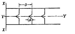
Fig. 6.12. AX is line of contact and scratch
is along line YY.
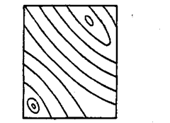
Fig. 6.13. Surface with two high/low spots.
Fig. 6.14. Surface worn at edges.
Fig. 6.9. Convex surface.
Fig. 6.14 here shows that surface in the middle is flat and at ends, it has got worn away
and has thus become convex. This type of surface is generally encountered in the workshop as
the surface tends to round off from the edges due to lapping, wear etc.
Similarly other surfaces can also be predicted if these general rules are followed.
