6.4
The essential equipment for measurement by light wave interference is a
monochromatic light source and a set of optical flats. An optical flat is a circular piece of optical
glass or fused quartz having its two plane
faces flat and parallel and the surfaces
are finished to an optical degree of flat-
ness. Optical flats vary in size from 25
mm diameter to about 300 mm diameter.
Quartz flats have high wearing qualities
and have 200 to 400 per cent great wear-
ing qualities than the optical glass.
Quartz has minimum expansion due to
heat and the thickness used insures
freedom from distortion in use. The im-
portance of optical flats is apparent in
lightwave measurement because all in-
spection operations are performed with
reference to the master surfaces of the
optical flats. (For more details about
optical flats, refer Art. 6.10).
If an optical flat is placed upon another flat reflecting surface (without pressure) it will
not form an intimate contact, but will lie at some angle 0 making an inclined plane. If the
optical flat be now illuminated by monochromatic source of light, the eye if placed in proper
position, will observe a number of bands. These are produced by the interference of the light
rays reflected from the lower surface of the top flat and the top surface of the lower flat through
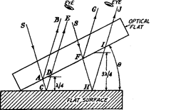
the very thin layer of air between the flats. In Fig. 6.5, the angle 6 between the two flats is
shown exaggerated too much. S is the source of monochromatic light. At point A, the wave of
incident beam from S is partially reflected along AB and is partially transmitted across the
air gap along AC. At C, again the ray is reflected along CD and passes out towards the eye
along CDE. Thus the two reflected components, reflected at A and C are collected and
recombined by the eye, having travelled paths whose lengths differ by an amount ACD.

Fig. 6.5. Flatness testing by interferometry.
If the path lengths of the two components differ by an odd number of half wavelengths,
then condition for complete interference is achieved. If the surface is perfectly flat, then
condition of complete interference is satisfied in a straight line across the surface as the surface
at right-angles to the plane of the paper is parallel to the optical flat. Therefore, a straight
dark line will be seen passing through point C. Consider another ray incident along path SFH.
Again this ray is also splitted into two components. It is obvious that the path difference of the
two component rays will keep on increasing along the surface due to angle 9. Thus if the path
difference FHI be 3X12 or the next odd number of half wavelengths, then interference will occur
and a similar fringe will be seen. Next when path difference is 5K/2, again there will be another
dark fringe. At the intermediate point between the points C and H, the path difference will be
an even number of half wavelengths and the two components will be in phase producing a light
band.
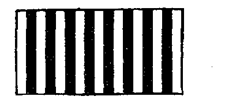
Thus, in case of a perfectly flat surface, we will have pattern of alternate light and dark
straight lines on the surface, as shown in Fig. 6.6. Any deviation from this pattern will be a
measure of the error in the flatness of the surface being inspected.
6.4.1. Checking the Flatness by above Method. Referring again to Fig. 6.5, if 0 is
very small, (which is generally the case, as it is made due to some particles between optical


Fig. 6.6. Interference pattern on
perfectly flat surface.
Thus it is obvious that each adjacent fringe represents a change in elevation of the work
surface relative to the optical flat of X/2 and total change in elevation from point of contact to
the outermost fringe will be n x X/2, if it contains n number of adjacent fringes.
Now there are four possible cases when the contact between the optical flat and the work
surface occurs at one point only.
(i) If the surfaces are perfectly wrung together, then no air gap exists and no fringe
pattern will be observable.
(ii) If angle 0 is increased, then points C and H will be closer together and fringes are
brought closer together.
(iii) If angle 0 is reduced, then fringes spacing increases as the points C and H will occur
at greater distances.
(iv) If 0 is made too large, then fringes will be closely spaced as to be indistinguishable
and no observable pattern will be visible.
The viewing angle, i.e. the angle at which the bands are viewed should be 0°, i.e. line of
sight should be perpendicular to the reference surface of the optical flat. If viewing angle is
30°, then 3 fringes may be seen as 2.5, causing an error of nearly 15%. If it is 45°, 3 fringes
may be read as 1.75, causing error of nearly 40%.
In practice, on the surface to be tested,we have large number of hills and valleys and in
these circumstances it is impossible that contact between the surface and the optical flat will
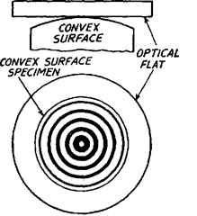
occur at one point only. Rather the contact will be made at a large number of hills. If the optical
flat is resting on any hill, then it will just behave as if it were placed on some spherically convex
surface. In such a case, the contact is made at the central high point and in centre a bright
circle will be visible. Around it, there will be concentric dark and bright circular fringes. As
the distance from the centre increases, the separation between optical flat and surface keeps
on increasing and the fringes become narrow and more closely spaced as shown in Fig. 6.7.

Fig. 6.7. Fringe pattern as observed
through optical flat.

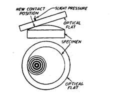
Fig. 6.8. Test for convex surface.
For testing any flat surface, we have to lower down the level of hills. Actually by naked
eye, one can’t differentiate between the hill and valley in case of fine finished surfaces. And
the fringe pattern obtained by concave surface will be same as in case of convex surface.
To distinguish between the two conditions of convex and concave surfaces one edge of
the optical flat is lightly pressed. In case of convex surface, by light pressure the optical flat
will rock on a new high spot and the centre of the fringe pattern will move as shown in Fig.
6.8. Also the outer fringes will move closer together.
In case of spherically concave surface, the flat is resting on a line passing around the
surface and on lightly pressing the edge of the optical flat, the edge line does not move as the
pressure is varied. Rather, light pressure at the centre will cause the optical flat to be deflected
and will become more nearly parallel to the concave surface, thus reducing the number of
fringes observed.
Thus if by light pressure, the centre of fringes is displaced and the fringes are brought
closer, it is convex (hill) surface and the level at that place must be lowered down to form a flat
surface. If by light pressure the number of fringes is reduced and the fringes move apart, it is
(valley) concave surface.
Sometimes surface might not be perfectly convex or concave. So the study of various
patterns of fringes produced for different types of surfaces is very essential.
Interferometry Applied to Flatness Testing (Metrology)
Next post: Surface Contour Test (Metrology)
Previous post: Light Sources for Interferometry (Metrology)
