6.8.
This article is based on a similar article appearing in magazine “Machine Design” Vol.
47 No. 4. The measuring capacity in interferometers with lamp as source of light is limited
because it is not possible to maintain the sharpness of interference fringes beyond certain
distance due to the size of the lamp. Laser interferometer uses A.C. laser as the light source
and thus enables the measurements to be made over longer distance because it is possible to
maintain the quality of interference fringes over long distances when lamp is replaced by a
laser source. It must be understood that white light emitted by a lamp is combination of waves
at different frequencies but laser generates a continuous train of light waves, resulting into
high coherence. Laser represents a source of intensely monochromatic optical energy, which
can be collimated into a directional beam. Also laser beam wavelength is exact and pure for
highly accurate measurements. It utilises the principles of both optical techniques and digital
electronics ; and is a highly accurate and versatile measuring system that can cope with
industrial environments. In case of AC laser interferometer (ACLI) position information is
carried as phase deviation rather than as a signal amplitude deviation, thus giving a much
improved signal to noise ratio over amplitude modulation, because the noise sources that affect
signal amplitude have little effect on phase. In this way, ACLI is much more tolerant of
environmental factors that attenuate the intensity of a laser beam, such as dust, smoke, air
turbulance etc. It requires no warm-up time or standby power.
Thus ACLI has the following advantages: high repeatability and resolution of displace-
ment measurement (0.1 um), high accuracy, long-range optical path (60 m), easy installation,
and no change in performance due to ageing or wear and tear. A single laser source can be
used for as many as six simultaneous measurements in different axes. However, it is very much
expensive ; since the basic instrument measures physical displacement in terms of wavelength
instead of traditional units, conversion instrumentation is required for conventional read out.
Highest possible accuracy is obtainable only by compensating changes in air pressure and
temperature which affect wavelength of the laser beam.
Fig. 6.31 explains the operation of AC Interferometer.

Fig. 6.31. AC interferometer.
It uses two frequency laser system, thus overcoming the shortcoming of d.c. laser
interferometer. Whereas the d.c. system mixes out of phase light beams of the same frequency,
the a.c. system mixes beams of two different frequencies thus permitting the distance
information to be carried on a.c. waveform. Use is made of the fact that the AC amplifiers are
insensitive to d.c. variation of a.c. inputs.
Two frequency Zeeman laser generates light of two slightly different frequencies with
opposite circular polarisations. These beams get split up by beam splitter B\: one part travels
towards B2 and from there to external cube corner where the displacement is to be measured.
It may be noted that mirror is not employed here like Michelson Interferometer, because mirror
alignment is a critical procedure. This interferometer, instead, uses cube-corner reflectors
(retroreflectors) which reflect light parallel to its angle of incidence regardless of retroreflector
alignment accuracy. Beam splitter B2 optically separates the frequency ft which alone is sent
to the movable cube-corner reflector. The second frequency f2 (optically separated) from B2 is
sent to a fixed reflector which then rejoins ft at the beam splitter B2 to produce alternate light
and dark interference flicker at about 2 Mega cycles per second. Now if the movable reflector
(external cube corner) moves, then the returning beam frequency will be Doppler-shifted
slightly up or down by Aft. Thus the light beams moving towards photo-detector P2 have
frequencies ft and (ft ± Aft) and P2 changes these frequencies into electrical signal. (Photocells
convert light-intensity variations into voltage pulses which can be processed by electronic
instruments to give the amount and direction of position change).
Photo detector Pj receives signal
from beam splitter Bx and changes the
reference beam frequencies ft and ft, into
electrical signal. An A.C. amplifier Ax
separates frequency difference signal ft -
ft and A2 separates frequency difference
signal [(ft - (ft ±A/)]. The pulse converter
extracts Aft one cycle per half wavelength
of motion. The up-down pulses from the
pulse converter are counted electronically
and displayed in analog or digital form on
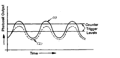
the indicator. It may be noted that output
in case of ACLI is in the form of pulses,
whereas in d.c. systems, the output is in
the form of a sinusoidal wave, the
amplitude (intensity) of which depends
upon laser aging, air turbulence or air
pollutant and thus the change of
amplitude leads to improper triggering and counting errors (Refer Fig. 6.32).
6.8.1.
Laser Interferometers and Automatic scale Measuring Interferometer.
It is felt that the present length standard (krypton 86) may eventually be replaced by the laser
(light amplification by stimulated emission of radiation) because the present light wave
standard has a potential accuracy of determination of perhaps 1 or 2 parts in 109. The principle
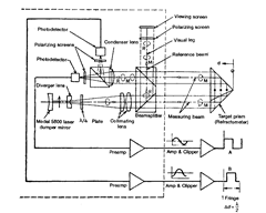
of the operation of laser-interferometer is demonstrated in Fig. 6.33 which has higher
accuracies for measuring greater lengths.
Fig. 6.34 shows a cutaway view of a laser interferometer.
For measurement purposes, present techniques utilize the gas laser, and in particular,
the helium—neon gas laser, married with a suitably designed interferometer. The great
advantage of the gas laser compared to other light sources is its coherency and strongly defined

(1) Counter operating, if amplitude of wave is above counter
trigger level.
(2) Counter disabled by small amplitude change of
sinusoidal wave.
Fig. 6.32

Fig. 6.33. Schematic arrangement of laser interferometer.
fringe pattern over long optical paths. The gas laser is already established as a practical
length-measuring tool in most of the national bureaus, Fig. 6.35.
Precision scales up to 1 metre in length are verified automatically in terms of a laser
wavelength determined by reference to the krypton 86 standard. The number of wavelengths
in each scale interval is determined using a laser interferometer and electronic counting. The
counts are punched onto paper tape which is processed by a computer to give a table of errors
for the scale intervals.
The gas laser wavelength also drifts over a period of time and is dependent on (i) the
conditions of the environment, (ii) on the adjustment of the reflecting mirror “chamber”, which
acts as an optical resonator for the helium—neon atoms. Latter can be adjusted very precisely
by using piezoelectric or magnetostrictive mirror mounts. Laser standard is, therefore, peri-
odically compared against the standard line of krypton-86.
6.8.2
Brief description of components involved
(i) Two frequency laser source. It is generally He—Ne type that generates stable
coherent light beams of two frequencies, one polarised vertically and one horizontally relative
to the plane of the mounting feet. The frequency stabilisation is based on Zeeman splitting of
the atomic levels involved in the laser action. Laser oscillates at two slightly different
frequencies by a cylindrical permanent magnet around the cavity. The two components of
frequencies are distinguishable by their opposite circular polarisations. Beam containing both

Fig. 6.34. Cutaway view of leser interferometer.

Fig. 6.35. Length measuring tool.
frequencies passes through a quarter wave and half wave plates which change the circular
polarisations to linear perpendicular polarisations, one vertical and other horizontal. Thus the
laser can be rotated by 90° about the beam axis (roll) without affecting transducer performance.
If the laser source is deviated in roll from one of the four optimum positions, the photo-receiver
signal will decrease. At a deviation of 45°, the signal will decrease to zero. The linearly polarised
beam is expanded in a collimating telescope, after which most of the beam is transmitted
through a 45° beam splitter and out of laser head.
(ii) Optical Elements:
(a) Beam splitters. These, (like partially silvered mirrors) divide the laser beam into
separate beams along different axes. It is possible to adjust the splitted laser’s output intensity
by having a choice of beam splitter reflectivities. To avoid attenuation it is essential that the
beam splitters must be oriented so that the reflected beam forms a right angle with the
transmitted beam, so that these two beams are coplanar with one of the polarisation vectors
of the input beam.
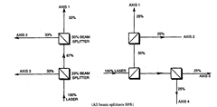
Fig. 6.36 illustrates the use of beam splitters to divide laser output equally along
different axes.

Fig. 6.36. Use of beam splitters to divide laser output equally.
(b) Beam benders. These are used to deflect the light beam around corners on its path
from the laser to each axis. These are actually just flat mirrors, but having absolutely flat and
very high reflectivity. Normally these are restricted to 90° beam deflections to avoid disturbing
the polarising vectors.
(c) Retro-reflectors. These can be plane mirrors, roof prisms or cube-corners. Cube-
corners are three mutually perpendicular plane mirrors, and in these devices the reflected
beam is always parallel to the incidental beam. Each ACLI transducer axis needs at least two
retro-reflectors as explained in Fig. 6.37. All ACLI measurements are made by sensing
differential motion between two retroreflectors relative to an interferometer. Plane mirrors
used as retroreflectors with the plane-mirror interferometer must be flat to within 0.06 micron
per cm.
(iii) Laser head’s measurement receiver. During a measurement, the laser beam is
directed through optics in the measurement path and then returned to the laser head’s
measurement receiver which will detect part of the returning beam as fx – f2 and a doppler
shifted frequency component bf.
(iv) Measurement display. [Refer Fig. 6.37 (a)] It contains a microcomputer to compute
and display results. The signals from reference receiver and measurement receiver located in
the laser head are counted in two separate pulse counters and subtracted. Necessary calcula-
tions are made and the computed value is displayed. Other input signals for correction are
temperature, coefficient of expansions, air velocity etc. which can also be displayed.
6.8.3.
Various versions of ACLIs
(1) Standard Interferometer (Refer Fig. 6.37 (a)]. It is the least expensive and can be
used whenever possible. The measurement retroreflector for this interferometer is a cube

corner. Displacement is measured between the interferometer and the cube corner. Either one
or both could move.
(a) Single beam Interferometer [Refer Fig. 6.37 (fc)]. It has the outgoing and returning
beam superimposed on each other, giving the appearance of only one beam travelling between
the interferometer and the retroreflector.
This interferometer operates functionally the same way as the standard interferometer,
but it is advantageous when space for optics and beam paths is limited. The interferometer
and retro-reflector for this system are considerably smaller than the standard system.
6.8.4.
Sources of Errors.
The various sources of errors in the use of ACLIs are :
(i) uncertainty in the refractive index of air (velocity of light).
(ii) alignment (cosine error).
Avoiding Sources of Errors
(i) Velocity of light (VOL) compensation. It has been found that wavelength of laser
changes by about one part per million for every :
(a) atmospheric pressure change of 2.5 mm of Hg; i.e. if pressure varies by ± 20 mm of
Hg, wavelength varies by about ± 7.5 ppm ; in other words, if axis of travel is 2 metres, this
pressure change could cause an error of ± 15 microns.
(b) air temperature change of 1°C.
(c) relative-humidity change of 100%.
The best method to compensate for VOL changes is to take barometer, thermometer and
hygro meter readings and apply correction by referring to compensation tables.
(ii) Cosine error. As the ACLI measures component travel in the direction of laser
beam, and if two are not coincident, then error called cosine error will be introduced. To avoid
it, the axis of measuring device should be aligned with the axis of travel or object.
(iii) Beam Protection. Though the ACLI is quite tolerant of the beam disturbance ;
however the following types of disturbances should be avoided ;
(a) Beam must never be completely blocked by a solid object.
(b) Index of refraction of air path followed by a beam should be as uniform as possible
over the entire optical path, i.e. no temperature or pressure gradient in air path.
