5.7.
These comparators depend for their operation on Wheatstone bridge circuit. In d.c.
circuit, a change of balance of the electrical resistance in each arm of the bridge is caused by
the displacement of an armature relative to the arm under the action of the measuring plunger.
Once out of balance is caused in the bridge, it is measured by a galvanometer graduated to
read in units of linear movement of plunger. This circuit is operated by battery. For the bridge
to balance, the ratios of the resistances in two arms must be equal.
If alternating current is applied to the bridge, the inductance and capacitance of the
arms must also be accounted for along with resistance. In actual measuring instruments, one
pair of inductances is formed by a pair of coils in the measuring head of the instrument. The
movement of the plunger displaces an
armature, thus causing a variation in
the inductance of a pair of coils forming
one arm of a.c. bridge. The arm carries
the armature (Fig. 5.20) and the induc-
tance in the coils is dependent upon the
displacement of the armature relative
to the coils. There are other refinements
in actual instrument such as an electri-
cal method of zero adjusting and a
switch to change the magnification. The amount of unbalance caused by movement of measur-
ing plunger is amplified and shown on a linear scale. Magnifications of the order of x 30,000
are possible with this system. Commonly used instruments are Electrichek, Electricator,

Fig. 5.20. Electrical comparator based on a.c. bridge.
Electrigage, Electrolimit and Electronic Measuring Equipment. A brief description of a few of
these is given from 5.7.2 to 5.7.7.
5.7.1.
Electrical Comparators.
Electrical comparators are also known as electro-
mechanical measuring systems as these employ an electro-mechanical device which converts
a mechanical displacement into electrical signal.
Fig. 5.21 shows a block diagram of an electro-mechanical measuring system.
![]()
Fig. 5.21. Block diagram of an elementary electro-mechanical measuring system.
Linear variable differential transformer (LVDT) is the most popular electro-mechanical
device used to convert mechanical displacement into electrical signal. It, in effect, is a
transformer consisting of three symmetrically spaced coils carefully wound on an insulated
bobbin. It works on mutual inductance principle and consists of a primary coil wound on an
insulating form (bobbin) and two identical secondaries symmetrically spaced from the primary.
AC carried excitation is ap-
plied to the primary and two
secondaries are connected ex-
ternally in a series opposition
circuit. The lead wires exit
through an opening in the
outer shield, usually in the
end-cover washers. A cylindri-
cal shield of ferromagnetic
material is spun over the
metallic end-washer after the
windings have been vacuum-
impregnated with a potting
compound suitable for the ap-
plication environment. The
finished transformer there-
after becomes quite imper-
vious to humidity or ordinary
magnetic influences. The
device thus also becomes ex-
tremely rugged and reliable. There is a non-contacting magnetic core, made from a uniformly
dense cylinder of nickel-iron alloy, carefully annealed to improve and homogenise its magnetic
permeability, which moves in the centre of these coils wound on the insulating form and the
motion of this core varies the mutual inductance of each secondary to the primary, which
determines the voltage induced from the primary to each secondary. If the core is centered in
the middle of the two secondary windings, then voltage induced in each secondary winding
will be identical and 180° out-of-phase, and the net output will be zero. If the core is moved off
middle position, then the mutual inductance of the primary with secondary will be greater
than the other, and a differential voltage will appear across the secondaries in series. For off
centre displacements within linear range of operation, the output is essentially a linear
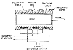
Fig. 5.22. Schematic Arrangement of LVDT
(core-shown in the middle position).
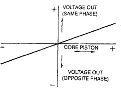
Fig. 5.23. Phase referenced output voltage of LVDT.
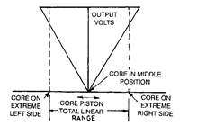
Fig. 5.24. Absolute value of output voltage of LVDT.
function of core displacement. The various unique features of LVDT are : Due to no physical
contact between the core and coil its mechanical components do not wear out; as a result the
friction is absent and true infinite resolution with no hysteresis is obtained. The small core
mass and the lack of friction enhance response capabilities for dynamic measurements and
thus it becomes very suitable for taking measurements for on-line machining. Further as it is
not affected by overload, its reliability is high.
5.7.2. Electronic Gauging. The electronic Gauging System is designed to fulfill the
increasing demand for equipment particularly suited to the accuracy and versatility required
by up-to-date engineering practice.
5.7.2.1. Principle of Operation. The principle of operation is shown in Fig. 5.25. The
movement at the probe tip actuates inductance transducer which is supplied with an alternat-
ing current from the oscillator.

Fig. 5.25. Principle of operation in electronic gauging.
The transducer converts this movement into an electrical signal which is then amplified
and fed via an oscillator to the demodulator. The current in D.C. form, then passes to the meter
and the probe tip movement is displayed as a linear measurement.
Various measuring and control units can be incorporated which provide for an extremely
wide range of single or multiple measurements to be made simultaneously.
Fig. 5.26 shows another design of electronic indicator capable of reading better than 1
micron. It consists of a gauging head and an amplifier. The mechanical movement of the contact
probe alters the output or voltage of the gauge head proportional to displacement. The small
alteration in voltage is amplified by means of a sensitive meter, calibrated in terms of units of
length. Switching selection enables a convenient range of magnification. Such an instrument
has many functional advantages like high magnification, range of magnifications, light
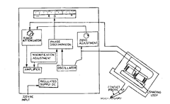
Fig. 5.26. Electronic indicator.
gauging force (40 grams or less), rugged construction, immediate response, unlimited ap-
plicability to inspection procedures.
5.7.2.2.
Differential Unit.
The differential gauge unit is used with two probes to show
the combination of two readings and by selection of the appropriate probe input sockets, may
add or subtract the readings obtained by the two probes. The sum, or difference of the two
![]()
(a) Taper measurement. (b) True diameter measurement (c) Measurement of length
independent of datum. irrespective of positional
tolerances.
Fig. 5.27. Showing the measurement of various dimensions.
readings is amplified and displayed on the unit as a single scale reading. The magnification
and output are exactly same as in the standard gauge unit, but an additional feature of this
unit is a switch which enables one of the two probes to be isolated.
Differential units have many applications, including the measurement of tapers ir-
respective of changes in diameter of the component; diameters, regardless of eccentricity and
also for the normal measurement of both diameter and run-out as shown in Fig. 5.27.
5.7.3.
Electricheck Gauges.
This gauge simply shows whether the dimension of a
component falls within a predetermined tolerance range without measuring the actual dimen-
sions. It can also be used as an automatic check on machines in operation to stop the tool when
the dimension is out of prescribed limits. It employs reed mechanism in its measuring head
and reeds are caused to bend when the floating (movable) block is moved. The bending
movement causes the extension arm to break an electric circuit. Electric contacts control signal
to indicate whether the dimension is within tolerance or not. The gauge has first to be set by
precision slip gauges to the maximum and minimum limits of tolerance.
5.7.4.
Electricator Gauges.
This gauge combines the advantages of both dial indicator
for actual measurement and tolerance signals in the form of sound or light.
5.7.5.
Electrolimit Gauges.
It combines mechanical gauging with electrical magnifica-
tion by Wheatstone bridge. The degree of magnification of instrument is adjustable and
arrangements for zero setting are also provided. This gauge eliminates the errors due to sense
of feel in taking measurements and provides the accuracy needed for statistical quality control.
It has wide range of applications and speed of gauging process is increased very much by its
use.
5.7.6.
Electronic Measuring Equipment.
This provides a reliable means for making
external and internal measurements with a remarkable accuracy and ease. This equipment
employs a highly dependable Wheatstone bridge circuit in the form of a strain gauge. Due to
the deflection of gauging point because of change of dimension, a minute change is experienced
in the electrical resistance of the bridge circuit. This creates voltage signals which are amplified
and they in turn operate the indicating meter. It can be used for a variety of internal and
external measurements and special attachments are provided to make it more versatile.
5.7.7.
The Electronic Comparator.
It is based on the principle of application of
frequency modulation or radio oscillation. A special ratio oscillator is used which produces
impulses of a definite value at a definite frequency. The frequency is controlled by the
measuring head. When the measuring head is applied to the part to be measured the frequency
of the instrument oscillator is modified because of the variation of the dimension from that of
the preset standard. The modified frequency is annuled by
suitable controls to restore it back to the basic value. The
measuring instrument dial is graduated directly in terms of
the physical standards of length which compare with the
electronic standards of wavelength. By using various adaptors
to suit the work, the comparator can be put to many applica-
tions such as external and internal gauging, flatness, testing,
thickness gauging, tube wall thickness, measurement of
electro-plate coating, gauging on curved or flat surfaces etc., to
a very high limit of measuring precision. In Fig. 5.28, the
comparator is shown being used as a thickness gauge. With
high frequencies, it is extremely sensitive to such variables, as
temperature, mechanical and electrical changes. Using different frequencies, the sensitivity
of the instrument can be easily changed and it is achieved by providing a multi-position switch.
5.7.8.
Digital Comparators
(Special features of digital comparator shown in
Fig. 5.29). Incremental measuring system with optoelectronic reading of a grid line glass scale.
Clear and high contrast digital display. Large measuring range and high resolution.
Compact design with integrated but separately accessible case for batteries. Con-
veniently placed operating elements for the various measuring functions. Measuring spindle
mounted in high precision ball bush guide, virtually friction free and without play. Screw-in
cable release for raising measuring spindle. Fitted with dampened lowering motion of spindle.
Contact point is fitted with ruby ball.
Highly versatile application. Can be combined with indicating hand measuring instru-
ments. Compact design with short mounting shaft and measuring spindle. Therefore insensi-
tive against overload.
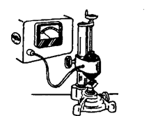
Fig. 5.28. Electronic comparator.
Resolution selectable 1 \im
Measuring range 10 mm
Measuring accuracy over
entire range ± 1 (*m
Measuring pressure 1 N
Max. travel speed
of spindle £ 0.5 m/s
Digital display LCD, height of
characters 8 mm
Power supply Choice of batteries
or net connection.
Advantages
Digital read-out on large and clearly defined
numerals.
Universal application by choice of various
measuring functions such as reset, preset, tolerance in-
dication, memory for maximum and minimum value.
Universal power supply by choice of batteries
or net connection.
High measuring accuracy by incremental
measuring system with optoelectronic reading of a grid
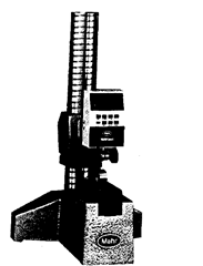
Fig. 5.29. Digital comparator.
line glass scale. Measuring system without mechanical components, therefore most accurate
and free of wear.
Small dimensions. Digital Comparators with measuring range of 10 mm fit into
practically all indicating hand measuring instruments.
Measuring spindle mounted in high precision ball bush guide virtually free of
friction and insured against cocking. The next to zero friction not only insures maximum
accuracy but also minimum hysteresis.
Corrosion-proof. Both mounting shank and measuring spindle are made of hardened
stainless steel.
Processing of measuring results by data exit for the connection of computers via
interface.
Measuring functions
A choice of various measuring functions is given by operating conveniently placed push
buttons or switches on the front and the side of the housing. The digital comparator is therefore
universally applicable.
Measuring function
Zero setting of digital display and
clearing of functions max/.min., tolerance
and store.
Storing of displayed measuring
results. This does not influence the inter-
nal pick-up of measuring values which is
continued.

Setting of tolerance limits. The
tolerance condition of any given part can be
determined instantaneously by observing
clear symbols for undersize, good and over-
size.
Memory for maximum and minimum
value. Peak values for outside diameter
checks. When performing this, simply
move part under probe and any deviation
from the preset nominal diameter is auto-
matically entered into memory. Same ap-
plies to minimum value.
Direction of counting reversible for
outside and inside measurements.
Data transfer from ASCII-data exit.
Digital Preset. Basic measurements up to
± 999,999 mm can be preselected. They are
automatically recognized at each measure-
ment.

5.7.9.
Indicating Snap Gauge
(Special features of snap gauge shown in Fig.
5.30). Measures cylindrical parts, such as shafts, bolts or spindles, thicknesses and lengths.
Rugged, forged steel frame with heat insulator. Measuring spindle mounted in extra
long guideway, retracts by lever control. Anvil adjusts with thumb screw via worm and rack.
Both measuring spindle and anvil made of hardened stainless steel, measuring faces carbide
tipped. Adjustable centre stop for automatic alignment.
Advantages
Direct indication of measuring results. Actual dimension of the part can be deter-
mined with absolute accuracy.
Versatility. Each gauge covers a large range. Within its limits it is quickly and easily
adjusted to any size and type of measuring application.
Maximum wear resistance by contact free positioning of measuring spindle plus
carbide tipped measuring faces.
Constant pressure by built-in compression spring which eliminates interference from
operator’s personal feel.
Indicating Instruments. Any dial indicator/comparator with 8 mm mounting shank
may be used.
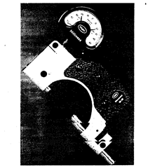
Fig. 5.30. Indicating snap gauge.
5.7.10.
Instruments for checking and presetting tools Including a projector and measuring system:
Measuring range X = 150 mm
(dia. 300 mm)
Z = 400 mm
Resolution 0.001 mm.
5.7.11.
Possible sources of errors in Electronic Instruments. The following possible sources of errors from electronic instruments have a bearing on working accuracy :
(i) Repeatability or short run ability to
repeat readings.
(ii) Drift. The indicator may be relied upon
for a datum but wanders over a period of time.
(iii) Temperature. The changes in tempera-
ture, apart from the temperature of the workpiece,
may alter the calibration of the instrument.
(iv) Magnetism. Some electronic instruments may be influenced by even the slightest
residual magnetism.
(v) Voltage fluctuation. Electronic indicator may be subject to short-run wandering due
to voltage fluctuation, specially in high magnification range.
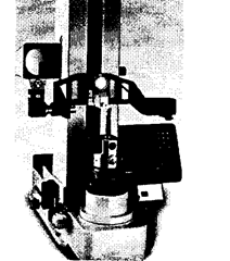
Fig. 5.31. Instrument for checking and presetting tools.
(vi) Loss of linearity. Periodic adjustments for linearity may be required, but short-run
changes stemming from unstable components can be dangerous in the inspection procedure.
(vii) Degree of linearly. Electronic indicator is comparator and can not be relied upon for
wider ranges.
There are, in addition, sources of error in the environment, such as dirt, oil, air film,
stability of the set-up, finish and geometry of the workpiece, deflection, angle of the probe tip
to the work, vibration, temperature, parallax, etc. not related to the instrument itself.
