5.6.
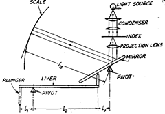
In mechanical optical comparators small displacements of the measuring plunger are
amplified first by a mechanical system consisting of pivoted levers. The amplified mechanical
movement is further amplified by a simple optical system involving the projection of an image.
The usual arrangement employed is such that the mechanical system causes a plane reflector
to tilt about an axis and the image of an index is projected on a scale on the inner surfac^ffta
ground-glass screen. Optical magnification provides high degree of measuring precision |Mp
to reduction of moving members and better wear resistance qualities. Optical magnificatioijis__
also free from friction, bending, wear etc. /rt^r~^ ?T /

Fig. 5.14. Principle of Optical Comparator.
The whole system could be explained diagrammatically by Fig. 5.14, which gives very
simple arrangement and explains the principle of above comparator.
In this system, Mechanical amplification = tyli
and Optical amplification = x 2.
It is multiplied by 2, because if mirror is tilted by an angle 60, then image will be tilted
by 2 x 66. Thus overall magnification of this system = 2 x (Z^i) (J4//3).
Thus it is obvious that optical comparators are capable of giving a high degree of
measuring precision owing to high magnification and the reduction of moving members to
minimum. Further these possess better wear resistance qualities as the only wearing members
are the plunger and its guide and the mirror pivot bearing. Another advantage of the optical
comparators is that provision of an illuminated scale enables readings to be taken without
regard to the room lighting conditions. The point of importance in optical comparator is that
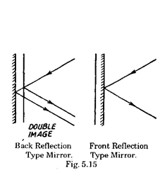
mirror used must be of front reflection type and not of normal back reflection type. In normal
back reflection type there are two reflected images, one each from front and back. Thus the
reflected image is not well defined one, as one bright and other blurred image are observed. If
front reflection type of mirror is used, then it requires considerable care in its use to avoid
damage to the reflecting surfaces.


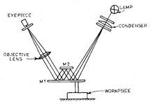
Fig. 5.16. The Optical arragnement of the Zeiss Ultra-optimeter.
5.6.1.
Zeiss Ultra-optimeter.
The optical system of this instrument involves double
reflection of light and thus gives higher degree of magnification. (Refer Fig. 5.16)
A lamp sends light rays to green filter, which filters all but green light, which is less
fatiguing to the eye. The green light then passes to a condenser which via an index mark
projects it on to a movable mirror Mi, whence it is reflected to another fixed mirror M2, and
then back again to the first moveable mirror. The second objective lens brings the reflected
beam from the first mirror to a focus at a transparent graticule containing a precise scale which
is viewed by the eye-piece. The projected image of index line on the graticule can be adjusted
by means of screw in order to set the zero. When correctly adjusted, the image of the index line
is seen against that of the graticule scale. The special end of the contact plunger rests against
the outer end of the first movable mirror so that any vertical movement of the plunger will tilt
the mirror. The extreme sensitivity of this instrument necessitates special precautions in its
operation to avoid temperature effects.
5.6.2.
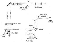
Zeiss Optotest Comparator (Refer Fig. 5.17).
This is the commercial measur-
ing instrument. This utilises a plunger tilted mirror, objective lens, prism and observing
eye-piece to provide a high degree of magnification. The mirror is mounted on a knife-edge and
it can be tilted about the fulcrum by any linear vertical movement of the contact plunger. A
beam of light passes through a graticule suitably engraved with a linear scale and the
movement of mirror causes this scale to move up or down past a translucent screen inside the
observing hood of the instrument. The eye placed near the eye-piece views the image of a small
scale engraved on glass after reflection from the plunger actuated mirror and the prism in the
plan view in Fig. 5.17.
In the focal plane of the eye-piece, a fine reference line (Index) is provided and the system
of lenses is so arranged that the image of the scale is projected in the same focal plane. Thus
with movement of scale the image can be measured with reference to the fixed line. The division
of the scale image opposite the index line indicates the amount of movement of contact plunger.
The image of the scale and the index line could also be viewed through a projection system.

Fig. 5.17. Zeiss optotest optimeter.
![]()
5.6.3.
Newall OMS Horizontal Optimeter.
This comparator is designed for very high
magnification. It can measure very accurately with great precision in horizontal direction. It
is very useful for measuring the internal and external dimensions of cylindrical gauges, screw
gauges and thickness gauges.
The instrument consists of a cast iron base with three levelling screws and a spirit level
for setting instrument horizontal. Two brackets are mounted on a transverse bar carried
through the base. The brackets are kept in alignment by a keyway and a spline, and carry an
optical measuring head and a tailstock respectively. The transverse bar is spiral grooved to
allow easy and quick lengthwise adjustment of bracket. There are other attachments also on
the base for various works. A vertically adjustable plunger with both titling and lengthwise
movements is also housed in the base. Inter-changeable heavy and light duty contact arms are
provided for internal measuring and a centre cradle for male cylindrical work.
5.6.4.
Eden-Rolt Millionth Comparator.
This comparator utilises both mechanical
and optical magnifications and thus is highly sensitive one. Its design is simple and economical.
The mechanical amplifying device
utilises a parallel strip support, con-
sisting of a fixed and a moving block
connected together by parallel thin
strips. The ends of fixed and moving
strips through two pointer strips
are connected to a pointer arm
which carries at its end a ring across
which is stretched a spider web. A

Fig. 5.18. Eden Rolt Millionth Comparator.
reference gauge is placed between a fixed anvil and movable measuring block. The slight
movement of moving block through pointer strip causes the pointer arm to be deflected as
shown in Fig. 5.18. The spider web at the end of the pointer arm is not viewed directly but it
is projected through an optical system on a scale as shown in Fig. 5.19. If’a’ be the distance
between the pointer strips and T be length of pointer arm, then for movement ’6′ of movable
member, angular deflection of pointer strips = (6/a) and linear displacement of web = (8/a) x /.
.-. Mechanical amplification = (6/a) x I + 6 = (Ha), which is of the order of 400.

Fig. 5.19. Optical system of Eden Rolt comparator.
The optical magnification is of the order of 50, thus overall magnification is around
20,000.
