ABSTRACT
A new method to accurately and reliably extract the actual Young’s modulus of a thin film on a substrate by indentation was developed. The method involved modifying the discontinuous elastic interface transfer model to account for substrate effects that were found to influence behavior even a few nanometers into a film several hundred nanometers thick. The method was shown to work exceptionally well for all 25 different combinations of 5 films on 5 substrates that encompassed a wide range of compliant films on stiff substrates to stiff films on compliant substrates. A predictive formula was determined that enables film modulus to be calculated as long as one knows the film thickness, substrate modulus and bulk Poisson’s ratio of the film and substrate. The calculated values of film modulus were verified with prior results that employed the membrane deflection experiment and resonance-based methods. The greatest advantages of the method are that the standard Oliver and Pharr analysis can be used and that it does not require the continuous stiffness method, enabling any indenter to be employed. The film modulus then can be accurately determined by simply averaging a handful of indents on a film/substrate composite.
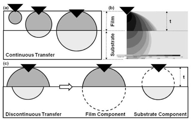
Figure 1: (a) Schematic illustrating the concept of continuous transfer of strain between the film and substrate, (b) numerical simulation indicating that strain is likely discontinuously transferred between the film and substrate, and (c) schematic showing how the film and substrate components are decoupled in the discontinuous elastic interface transfer model.
INTRODCUTION
Accurately assessing the properties of thin film coatings with modestly intrusive indents continues to remain a strong desire of the scientific and engineering communities. These measurements can be problematic as the deformation field emanating from the indent usually propagates in both the film and the substrate, rendering any property interrogated as a composite value influenced by both. Various experimental and theoretical-based approaches have been applied to decoupling these effects [1-20], yet a complete and accurate picture has been challenging to obtain. Recently, the authors proposed a new model called the discontinuous elastic interface transfer model [21] that accounted for an apparent discontinuity in elastic strain transfer at the film/substrate interface. The physical basis of this model is best illustrated in Fig. 1, which shows that values of strain are not numerically equivalent across the film substrate interface. Part (a) is a schematic of the spherically symmetric strain field emanating from an indent in a film/substrate composite that is representative of the interplay of stress and strain between the film and substrate in the leading models of Doerner and Nix [2] and Gao [3], see our prior work for a discussion on this point [21]. In this case there is a continuous transfer of strain from the film to the substrate, in other words, values of strain are numerically equivalent on both sides at the interface. However, our numerical simulations indicated that a discontinuity in elastic strain transfer should exist at the film/substrate interface, see Fig. 1(b) and (c). The new model was constructed based on this discontinuity by adapting the Doerner and Nix and Gao model forms; whereby, separate weighting factors were applied to account for the influence of the substrate in strain developed in the film and vice-versa, see Fig. 1(c). It has the following form,
Here, E’ is the composite modulus, Ef’ is the film![]() ‘ is the substrate
‘ is the substrate![]() and " f and " s are the weighting factors to account for the effects of the film on the substrate and substrate on the film respectively and are given as,
and " f and " s are the weighting factors to account for the effects of the film on the substrate and substrate on the film respectively and are given as,
where, t is the film thickness, h is the indent depth and #f and #s are the constants for the film and substrate respectively. This form resembles that of Doerner and Nix [2] and Gao [3] with the exception that they both applied a single weighting factor (" c.N and " Gao respectively) equally to each compliance component, see our prior work for a discussion on this point [21]. It should be noted that this form deals only with the film/substrate composite modulus (E) and not the reduced modulus (Er) that is affected by the indenter properties (Ef) as per (1/ED = (1/E) + (1/Ef). In most cases the indenter component is negligible and can be ignored because of the very low compliance of a diamond indenter. However, when the film/substrate compliance becomes comparable to diamond, the indenter component should be included.
The discontinuous elastic interface transfer model was compared to experimental data from thirteen different amorphous thin film materials on a silicon substrate and was found to match the all experimental curves with high fidelity. Furthermore, our prior work discovered that the # constants in each weighting factor were found to have physical significance in being numerically equivalent to the bulk scale Poisson’s ratios of the film (#f) and substrate (#s). The model proved to be adept at revealing the interplay between the film and substrate during indentation. Given that the model was investigated with only one substrate there was some question as to whether the model is applicable to other film/substrate combinations. This point is investigated in the following work employing 5 films and 5 substrates for 25 different combinations that encompass a wide range of compliant films on stiff substrates and stiff films on compliant substrate cases. It will determine whether the original discontinuous elastic interface transfer model is applicable to most film/substrate combinations.
EXPERIMENTAL PROCEDURE
In this work five different films and five different substrates were selected with a variable range of elastic moduli. The ability to deposit amorphous films was also a selection criterion so as to avoid microstructural effects and the films should not possess high modulus to hardness ratios to avoid loss of contact effects when employing the continuous stiffness method during indentation [22]. The films included chromium oxide (CrOx), amorphous silicon (a-Si), aluminum oxide (AlOx), aluminum nitride (AlN), and silicon carbide (SiC) and the substrates were amorphous silicon dioxide (SiO2), <100> germanium (Ge), <100> silicon (Si), <100> magnesium oxide (MgO), and <0001> sapphire (Al2O3), see Table 1 for material properties. The materials compose twenty five combinations of film/substrate modulus ratios. The substrates were all polished to a mirror surface to ensure uniform contact between the film and substrate. A Denton sputtering system was employed to deposit the films using DC or RF power. Here, optimum deposition parameters were determined from previous experiments [21] based upon those resulting in the "most" amorphous in structure. The substrate holder was rotated at a speed of 50 RPM to perform a uniform deposition. The achieved thickness of each film is listed in Table 1.
Table 1: Material properties and their source for the substrates and films selected for the indentation experiments.
|
Substrate |
Modulus (GPa) |
Poisson’s Ratio [ref] |
Thin Film |
Thickness (nm) |
Poisson’s Ratio [ref] |
||
|
SiO2 |
70 ± 4 |
0.17 (quartz) |
[39] |
SiC |
460 ±13 |
0.3 |
[44] |
|
Ge |
144 ± 7 |
0.27 |
[40] |
AlN |
1050±27 |
0.26 |
[45] |
|
Si |
173 ± 9 |
0.28 |
[41] |
AIOx |
260 ± 9 |
0.27 |
[43] |
|
MgO |
249 ± 17 |
0.23 |
[42] |
a-Si |
540 ± 6 |
0.25 |
[46] |
|
AI2O3 |
460 ± 28 |
0.21~0.27 |
[43] |
CrOx |
135 ± 15 |
0.25 |
[47] |
The indentation tests were performed with an MTS Nanoindenter XP system with a Berkovich type diamond tip. The continuous stiffness method (CSM) was employed to obtain Young’s modulus versus displacement with a harmonic displacement target set at 2 nm and a minimum thermal drift rate of 0.05 nm/s. The Poisson’s ratios of the films were assumed as the bulk values for all the amorphous thin films. For each film/substrate combination, 25 or more CSM tests were run with same final indent depth.
Quasi-static simulation of nanoindentation was performed using ANSYS 11 with the tip movement controlled by displacement. The model was built-up using 2-D elements and assuming material properties and film thicknesses listed in Table 1. Detailed information can be found in our previous work [21]. To simplify the simulation the film roughness and residual stress were assumed to be negligible.
RESULTS AND DISCUSSIONS
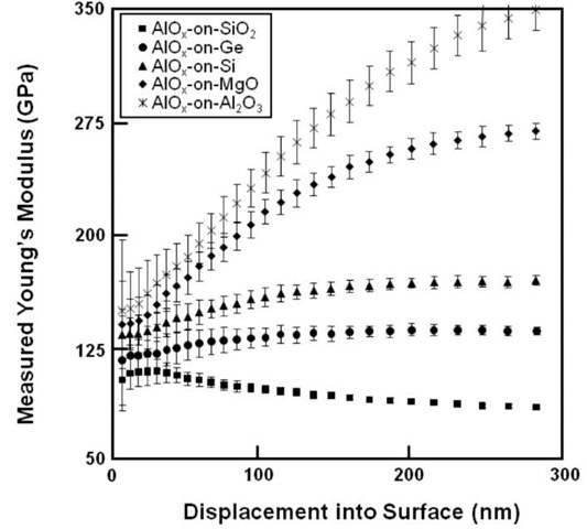
The raw indentation data for the 25 film/substrate combinations were calibrated and compared in groups of each film material. Fig. 2 shows the measured Young’s modulus-displacement curves of the AlOx films on the five substrates, encompassing a range of compliant-on-stiff to stiff-on-compliant film/substrate situations. Each curve exhibited a so-called "flat region," that many in the thin film indentation community consider to represent the Young’s modulus of the film, before increasing gradually to the substrate modulus with displacement into the surface, or decreasing when the substrate was softer. However, in this case, the value of the modulus in the flat region, Efat, for the AlOx film appears to strongly depend on the substrate modulus, increasing with increasing substrate modulus.
Figure 2: Plot comparing the measured Young’s modulus as a function of displacement for the AlOx films on different substrates.
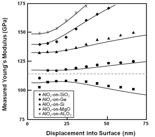
Figure 3: Plot illustrating the quality fit of the discontinuous elastic interface transfer model for the AlOx films and estimation of elastic homogeneity of the film/substrate composite (dashed line).
The other 4 films exhibited the same trend. Wei and coworkers have reported similar behavior in Al and W films on different substrates [23]. It should also be noted that we examined the curves for signs of loss of contact at low penetration depths in accordance with effects recently identified by Pharr et al. [22] and did not find any significant evidence of this effect. In applying our previously developed discontinuous elastic interface model, Eq. (1), each of the AlOx curves can be matched rather well, see solid lines in Fig. 3. Here, using the substrate modulus and Poisson’s ratios in Table 1, each AlOx/substrate combination yielded a different value for the film modulus, Ef’, which increased with substrate modulus (108 GPa for SiO2, 123 GPa for Ge, 138 GPa for Si, 141 GPa for MgO, and 149 GPa for Al2O3), see Table 2. These values match well with the value of E’fiat for each curve. The procedure was repeated for the remaining film/substrate combinations and the results are also listed in Table 2. It is clear from the data of all 5 films that the measured modulus in the flat region is not wholly determined by the film alone and that the substrate plays a significant role even very early in the indentation process. It is worth noting that while there were stiff-on-compliant and compliant on-stiff film/substrate combinations, the films and substrates used had Poisson’s ratios from 0.17 to 0.3, with none in the lower or higher range.
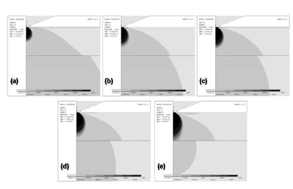
To further investigate the above conclusion that the substrate plays a role very early in the indentation process, finite element simulations were performed on all five AlOx/substrate combinations, see Fig 4. The simulations employed the material properties listed in Table 1 and a film thickness of 260 nm. Each simulation showed the elastic strain intensity distribution from an indent only 5 nm into the film/substrate composite for AlOx films on; (a) SiO2, (b), Ge, (c) Si, (d) MgO, and (e) Sapphire, with (b) through (e) representing soft-on-hard combinations.
Table 2 List of E’fiat values for each film/substrate specimen compared with the E’f values obtained from Fig. 4.
|
Values of Ef |
‘ and E„at |
(GPa) for the Films |
|
|
|
|
Substrate |
SiC |
AlN |
AlOx |
a-Si |
CrOx |
|
SiO2 |
196 ± 17 |
136 ± 13 |
108 ± 6 |
83 ± 6 |
64 ± 5 |
|
Ge |
222 ± 19 |
149 ± 11 |
123 ± 10 |
85 ± 7 |
80 ± 6 |
|
Si |
230 ± 23 |
146 ± 9 |
138 ± 13 |
88 ± 5 |
73 ± 5 |
|
MgO |
260 ± 16 |
153 ± 10 |
141 ± 20 |
87 ± 11 |
75 ± 14 |
|
Al2O3 |
281 ± 19 |
160 ± 14 |
149 ± 21 |
97 ± 7 |
72 ± 4 |
|
Estimated E’f from Fig. 4 |
259 |
144 |
121 |
82 |
64 |
|
E’fcalculated From Eq. 3. |
255 ± 19 |
140 ± 12 |
119 ± 9 |
84 ± 4 |
66 ± 4 |
Figure 4: Finite element analysis of the AlOx film/substrate composites showing the elastic strain distribution for an indent penetrating 5nm into each film; (a) SiO2, (b), Ge, (c) Si, (d) MgO, and (e) Sapphire.
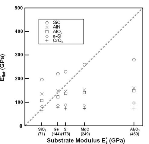
Figure 5: Plot E’fiat versus the substrate Young’s modulus for all 5 films illustrating that for each film, a point of elastic homogeneity or the actual film modulus can be suggested.
In all cases a discontinuous transfer of elastic strain was observed at the interface consistent with our model and previous work. It is clear that in all combinations a significant elastic strain field has developed in the substrate, even when the indenter has penetrated less than 2% of the film thickness. In case (a), the stiff-on-compliant combination, a significant amount of strain energy is absorbed by the more compliant substrate, resulting in the film appearing to possess less stiffness than it actually does. On the other hand, in the compliant-on-stiff cases, (b) through (e), the substrates absorb lesser and lesser amounts of strain energy as the substrate modulus increases. Here, the films appear stiffer than they actually are. This concept is consistent with the trend in AlOx E’flat values in Fig. 3 and in the data of the other films.
The actual Young’s modulus of the AlOx film should lie between the E’fiat of the SiO2 and Ge substrates. One may consider then the hypothetical case of elastic homogeneity existing between the AlOx film and substrate,both possess the same Young’s modulus.
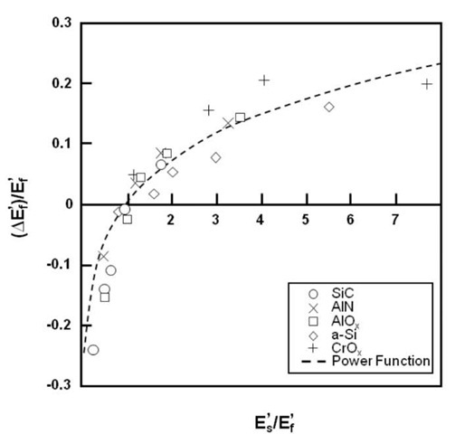
Figure 6: Plot of %E’f versus the substrate modulus, both are normalized by E’f to directly compare each film.
Saha and Nix [15] illustrated this experimentally for tungsten films on sapphire substrates. The dashed line in Fig. 3 represents this case as a rough interpolation between the compliant-on-stiff to stiff-on-compliant curves. Unfortunately, this interpolation is not an exact practice and a more precise method is desired. Using the concept of elastic homogeneity, one can plot the values of E’flat for the films versus the substrate modulus to better estimate the film modulus, see Fig. 5. Here the dashed line represents elastic homogeneity between the film and substrate. The trend of each film indicates that an intersection with elastic homogeneity should exist that identifies the film modulus. Linear regression was employed to identify these intersections, which are listed in Table 2. However, given the variability of the data, it is not clear that this is the most appropriate method. Furthermore, it is desired to obtain the Young’s modulus of the film from a handful of indents on a single film/substrate composite rather than depositing and indenting the film on several substrates. With any elastically mismatched film/substrate composite there will exist a difference between the film modulus and the measured modulus in the flat region, $E/, such that $E’ = E’fi„, -E’, that scales with the film/substrate mismatch. Values of $Ef’ were calculated using the film values estimated in Fig. 5 and the flat region values in Table 2. One can plot this difference versus the substrate modulus to assess whether the trend can be predicted and by normalizing both with the film modulus the different films can be compared, see Fig. 6. The data from all of the films appear to follow a uniform trend with the top half of the plot containing compliant-on-stiff combinations and the bottom half stiff-on-compliant combinations. A power function can be used to describe this behavior, and in conjunction with Eq. 1 lead to,
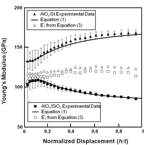
Figure 7: Experimental curves for AlOx films on Si and SiO2 substrates showing the uniformity of film modulus calculated from each data point with Eq. 3.
Here, the factor accounting for the early influence of the substrate is the ratio of the film to substrate modulus to the 0.1 power. It is unclear at this time as to the physical basis of the 0.1 power, but it matches the experimental data rather well for all 25 film/substrate combinations. This equation encompasses all aspects and enables the film Young’s modulus to be extracted from a single indent as long as one knows the film thickness, the substrate modulus, and the bulk Poisson’s ratios of the film and substrate.
The Young’s modulus of all of the films studied can be determined from the experimental data for any single film/substrate combination. Fig. 7 shows application of it to the AlOx films for the Si (compliant-on-stiff) and SiO2 (stiff-on-compliant) substrates. The solid line is the original equation, Eq. 1, for the discontinuous elastic interface transfer model and the open symbols are the calculated film modulus for each data point using the modified version, Eq. 3. The calculated values of the AlOx film are relatively uniform with displacement into the surface for both substrates. Both also agree fairly well with less than two percent difference between their average values for the two substrates. The average values were calculated for all five films on all substrates and are listed in Table 2. The modulus from this method agrees well with that estimated from Fig. 5.
This developed model appears adept at describing the complex interaction between the film and substrate during indentation. It was shown to work for amorphous and crystalline films with the wide range of film/substrate combinations investigated. Although most of the films investigated here where relatively hard in terms of plastic behavior, the results with gold and the soft alloys FeB and Metglas films in our prior work [21] indicate promising application to a variety of material classes. The method appears to provide a straightforward opportunity to accurately assess the Young’s modulus of a film or coating from mildly intrusive indents and employing the standard Oliver and Pharr method [38], while not requiring continuous stiffness measurements. The model though does not consider effects from residual stress or pile-up/sink-in. It may however, offer new opportunity to study these effects in more depth.
CONCLUSIONS
Indentation tests were conducted on five films on five different substrates and revealed that the so-called "flat" region often seen in the Young’s modulus versus displacement signatures of many indented films was not entirely representative of the film response alone. By tracking the response of each film on the different substrates, the magnitude of this flat region was found to depend and scale with the substrate modulus. Furthermore, the data indicated that the substrate significantly influenced the mechanical behavior even at penetration depths less than 2 % of the film thickness. All 25 film/substrate combinations were found to follow a consistent trend and a power law description of behavior was determined. This formula was incorporated into the discontinuous elastic interface transfer model of thin film indentation and was shown to be adept at extracting the actual film modulus from the experimental data while employing the standard Oliver and Pharr analysis. It also does not require the continuous stiffness method, enabling virtually any existing indenter to employ it. The values matched rather well and confirm the validity of extracting Young’s modulus of indents in film/substrate composite with high fidelity.
