This section discusses the IPv6 routing operation using route6d. In a FreeBSD/KAME box, the route6d daemon can be started from the rc script executed at boot time, thereby enabling the routing and forwarding functions of the box whenever the box restarts. The configuration parameters of the program and other related information such as address information could be specified from the terminal application directly, but it is more usual to define these configuration parameters in the /etc/rc.conf file and use the rc script to start the daemon.
The detailed usage of the route6d program is not discussed in this topic.
As discussed in Section 1.4, the RIPng protocol is not designed to operate for a large and complex IPv6 network. This section discusses RIPng operation for the following simple network configurations.
1 A leaf network
2 A simple loop network
3 A hierarchical network
A Leaf Network
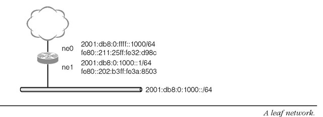
The simplest case of operating route6d is the case where there is only one local subnet. Figure 1-55 shows the network configuration used in this subsection.
The network prefix of the leaf network is 2001:db8:0:1000::/64. There is one router which connects the network and the upstream network. In this case, all routing information will come from the upstream router. The route6d program on the boundary router needs to advertise the routing information of the leaf network so that packets sent to this leaf network will be forwarded properly. In this configuration, the routing information for 2001:db8:0:1000::/64 needs to be advertised from the router.
FIGURE 1-55
When operating a router, all address configurations on the interfaces of the router must be done manually. In this case, we will assign 2001:db8:0:1000::1 on the ne1 interface and 2 0 01 :db8:0:ffff::1000 on the ne0 interface of the router.
The following command sequence will complete all of the configuration for this case.
The ifconfig command assigns an interface address and at the same time the network direct route is added statically in the routing table maintained in the kernel. In the above case, 2 0 01 :db8:0:1000::/64 and 2001 :db8:0:ffff::/64 are added after assigning addresses. The two anycast addresses mean the subnet-router anycast address for the subnet prefix, which all IPv6 routers must configure.The address consists of the network prefix and an all-zero interface identifier.
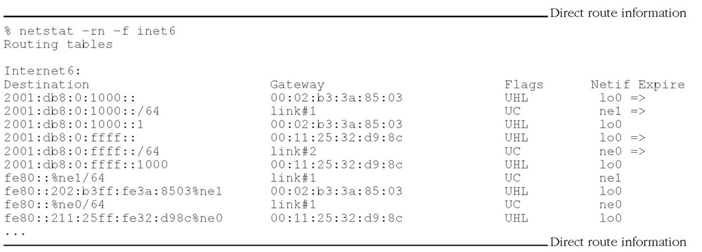
Listing 1-64 shows the routing table after the address assignment. Note that some lines are intentionally omitted from the output described in the listing because these are unnecessary in the following discussion.
Listing 1-64
There are two network routes in the routing table. One is 2001:db8:0:1000::/64 via ne1 and the other is 2001:db8:0:ffff::/64 via ne0, which are both installed during address configuration processes. At this time, the router can only reach those two networks since it does not have any route information to other networks.
On invocation, route6d starts receiving routing information from other RIPng programs connected through its network interfaces. Also, it starts sending routing information it has in its routing table. Listing 1-65 shows the routing table after the route6d program started.
Listing 1-65
We see three new routing entries in the example. The first one is a routing entry for the default route. All packets received on this router will be forwarded to fe80 :: 202 :b3ff:fe3a:87d9%ne0 if there is no more specific routing information against the destination address of the packets. fe80 :: 202 :b3ff:fe3a:87d9%ne0 is given via RIPng response messages, which is usually the source address of the message but can also be specified as an explicit next hop address. The other two are the routing information for the 2 0 01 :db8:0:2000::/64 and 2001 :db8 : 0 : 3000 ::/64 subnets. Note that such specific routing information may not appear when route aggregation takes place. In this case, these two specific routes can be aggregated to the default route. Whether the routing information is aggregated or not depends on the configuration of upstream routers.
All of the above configurations can also be done by setting up the /etc/rc.conf file. Once the configuration is confirmed to be correct, rc.conf should be prepared so that the same configuration will be done whenever the router reboots. Listing 1-66 shows a sample rc.conf file for this configuration.
Listing 1-66
The ipv6_gateway_enable variable enables the IPv6 forwarding function. A node never forwards packets unless the variable is set to YES. The ipv6_router_enable variable enables a routing daemon program. The default routing daemon program is route6d. The following ifconfig_* variables set interface addresses as described in the example above. The last two rtadvd_* variables are not discussed in this section, but they are usually required for router configurations. A router starts sending Router Advertisement messages when the rtadvd_enable variable is set to YES. The message is used by IPv6 hosts to autoconfigure their IPv6 addresses and to install a default router. The rtadvd_interface variable specifies the network interfaces to which the messages are sent. This example configuration just specifies ne1 since it is the only interface to the leaf network where Router Advertisements are necessary.
A Simple Loop Network
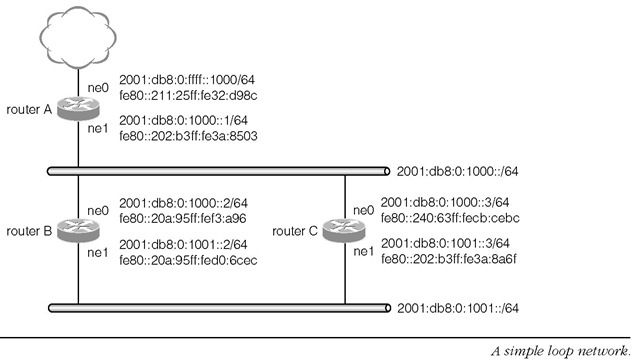
The route6d daemon can handle several networks which make a loop topology. As have already been discussed, however, RIPng is not designed to support a very complex network. Such a loop network should therefore be as simple as possible. Figure 1-56 is a sample loop network discussed in this section.
There are two networks in the sample network, one is 2001:db8:0:1000::/64 and the other is 2001:db8:0:1001::/64. The two routers B and C construct a network loop. The loop network is connected to the outside network via router A.
In this case, there are two routes from router B to reach the outside network. One route is router A via the ne0 interface and the other is router C via the ne1 interface. Similarly, router C has two routes. If router B chooses to send all packets which are destined to the outside network to router C and router C chooses router B to send packets for outside networks, packets can never reach their destination.
FIGURE 1-56
RIPng handles such a case and installs proper route information based on the route information received from neighbor routers.
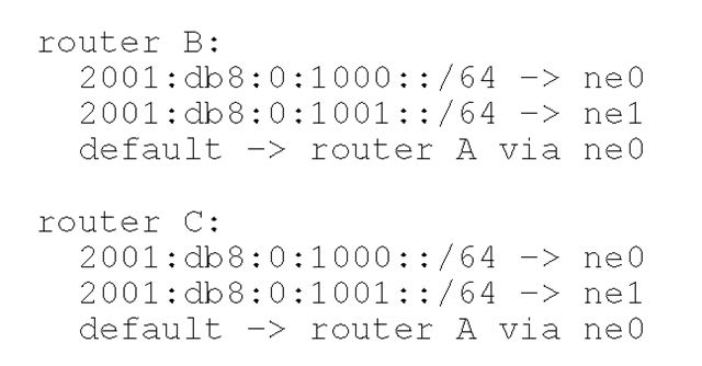
In this particular case, routers B and C will have the following route information.
In the above expression, -> denotes that the packets covered by the prefix information on the left-hand side are sent or forwarded to the network interface or the node written on the right-hand side.
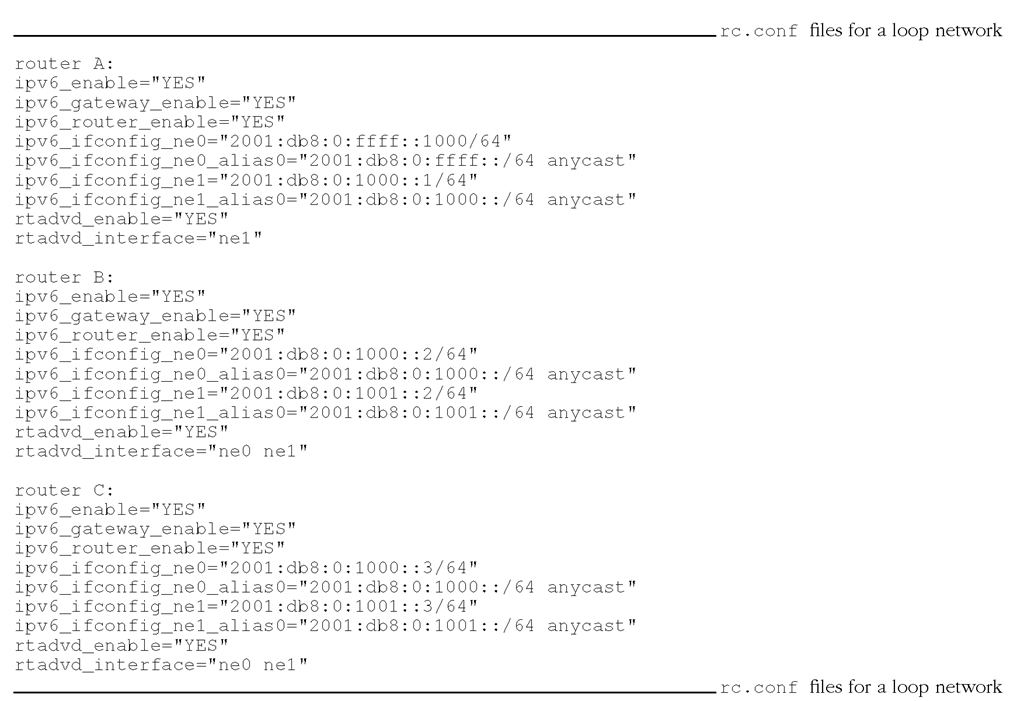
The startup configuration in the /etc/rc.conf file for this network is shown in Listing 1-67.
Listing 1-67
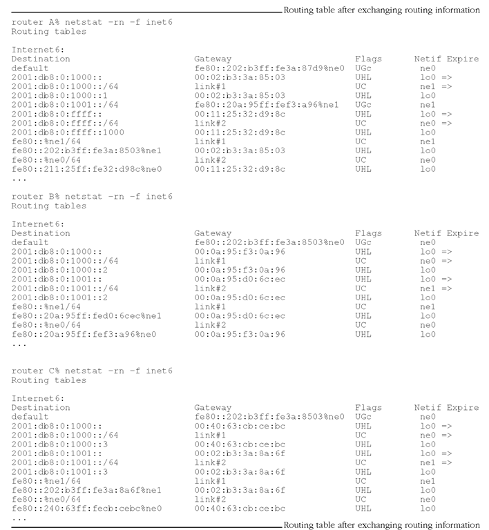
Once the routing information becomes stable, each router will have the routing table shown in Listing 1-68.
Listing 1-68
Router A forwards all packets whose destination address is neither 2 0 01 :db8:0:1000::/64 nor 2001 :db8 : 0 : 1001 ::/64 to the ne0 interface as a default route. Packets sent to 2001 :db8 : 0 : 1000 ::/64 or 2001 :db8 : 0 : 1001 ::/64 can be forwarded to either router B or router C. In this case, router B is chosen.
Each of routers B and C has two direct route entries. These routers are connected to 2 0 01 :db8:0:1000::/64 and 2001 :db8 : 0 : 1001 ::/64 directly and have routes to them via the ne0 and ne1 interfaces, respectively. The route to other networks is set to router A whose address is fe80::202:b3ff:fe3a:8503 through the ne0 interface as a default route.
A Hierarchical Network
When many subnetworks need to exchange route information, the entire network must be carefully designed. Basically, each entry of routing information is generated per one subnetwork; 100 routing entries will be generated for 100 networks by default. When considering routing information exchange, however, it is better if the number of routing entries can be reduced for efficiency. A routing entry can be aggregated when routing prefixes from downstream networks can be included in one larger routing prefix. For example, prefixes 2001:db8:0:1::/64 to 2 0 01 :db8:0:ff::/64 can be aggregated to 2001 :db8:0::/56. Note, however, that the less specific routing entry, e.g., 2001 :db8:0:1::/64 in this case, must not be used in other networks.
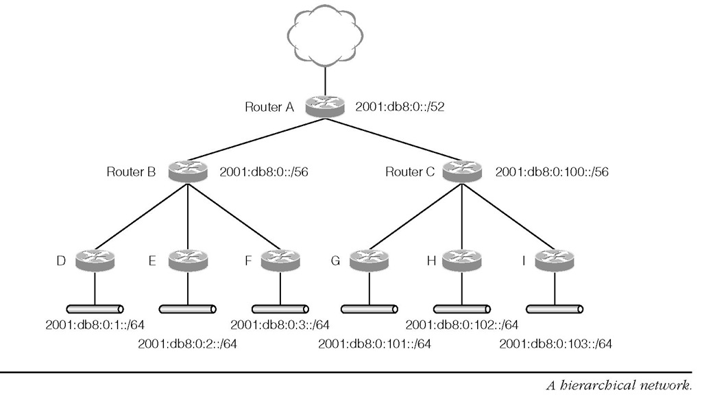
Figure 1-57 shows a sample hierarchical network where route aggregation is effective. The topology has 6 leaf networks. The three subnet prefixes on the left-hand side are 2 0 01 :db8 : 0 : 1 ::/64, 2001 :db8:0:2::/64 and 2001 :db8:0:3::/64, which are reached via routers D, E and F, respectively. The three subnet prefixes on the right-hand side are 2 0 01 :db8:0:101::/64, 2001 :db8 : 0 :102 ::/64 and 2001 :db8:0:103::/64 that can be reached via routers G, H and I, respectively. The first three networks are connected to router B and the latter three are connected to router C. Routers B and C are connected to router A.
In this case, there will be 6 routing entries without route aggregation, but the first three routes can actually be aggregated to 2001:db8:0::/56 and the latter three can be aggregated to 2001:db8:0:100::/56 (unless the other addresses covered in the aggregated prefix are used elsewhere).
FIGURE 1-57
These two aggregated routes are also aggregated to 2001:db8:0::/52 at router A (likewise). As a result, the 6 routing entries can be aggregated to only 1 entry. Yet another network can be added without increasing the number of route entries using this hierarchical network. For example, adding a subnet with prefix 2001:db8:0:4::/64 under router B does not increase the number of advertised route entries from router B since the new route information is aggregated by the router. There can be at most 256 subnetworks under routers B and C without any additional route information advertised from router B or C to the upstream router. Similarly, a new second-level router can be added under router A without causing additional route information advertised from this router. It suffices to introduce a new router which advertises, for example, 2001:db8:200::/56 under router A, since router A aggregates all route information covered by 2 0 01 :db8:0::/52.
The -A command line option of route6d is used to aggregate route entries. In the example shown in Figure 1-57, router B should invoke route6d as follows.
The interface name after the aggregated prefix specifies the interface to which the aggregated routing information is advertised. Similarly, routers A and C need to specify 2 0 01 :db8:0::/52 and 2001 :db8:0:100::/56 for the -A option, respectively. Listing 1-69 shows the corresponding startup configuration for router B.
Listing 1-69
In this example, router B does not have a global IPv6 address on the upstream interface. Since interior routing protocols can generally run using link-local addresses only, a global prefix does not have to be assigned to networks that do not contain IPv6 hosts.
