The BGP-4 protocol as defined in [RFC4271] is an exterior routing protocol that is mainly deployed between different autonomous systems (ASs). Since the original BGP-4 specification assumes the routing protocol operates over the IPv4 network, the routing messages carry only IPv4 routes. [RFC2858] updates the BGP-4 specification to support additional protocols such as IPv6. The extended BGP is commonly known as BGP4+. The specific use of BGP4+ by IPv6 is documented in [RFC2545]. We will use BGP4+ to refer to BGP4+ as deployed in the IPv6 network. We will also use the terms BGP4+ and BGP interchangeably for the remainder of this topic.
In the context of BGP4+, each AS has an Autonomous System Number or ASN. The ASN can be either a public ASN or a private ASN. A public ASN is a globally unique identifier and is assigned by an organization such as RIR or NIR. The IANA has reserved AS64512 to AS65535 as private ASNs. [RFC1930] discusses ASN in detail.
RIR stands for the Regional Internet Registry, which is responsible for the allocation and management of IP adresses and ASNs for a specific region of the world. Today there exist five RIRs: AfriNIC (Africa), APNIC (Asia Pacific), ARIN (North America), LACNIC (Central and South America), and RIPE-NCC (Europe).
NIR stands for the National Internet Registry, which is responsible for IP address allocation and management for a specific country.
BGP4+ uses the path-vector algorithm and solves the routing loop detection problem by including the path to the destination in the route message. When a BGP4+ router receives a route update, a router will update the path information to include its ASN before redistributing that route to other ASs. Since BGP4+ is an exterior routing protocol, routing information is exchanged among ASs, each with a different routing policy that governs what information could be made externally visible. For this reason, the path information carried in the route message is a list of ASNs instead of a list of specific routers in order to hide the internal topology of each AS on that path. Consider the example given in Figure 1-15.
As illustrated in the figure, each router records its ASN in the route message before distributing that route to another router. But first, each router must validate the received route message by examining the path information and verify that its ASN is not present in the path.
FIGURE 1-15
Routers RT-2 to RT-7 accept the received route message according to this rule. RT-8 finds its ASN in the route message originated from RT-7, therefore detecting the routing loop. In this case RT-8 rejects the advertised route from RT-7, thus breaking the loop.
BGP4+ Operation
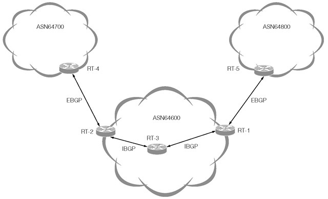
BGP4+ operates over TCP. A BGP4+ router establishes a peering relationship with another BGP4+ router by establishing a TCP connection to port 179 of that other router. The two BGP4+ routers are called BGPpeers, also known as BGP speakers. Typically BGP4+ is deployed for inter-AS routing, but large organizations and enterprises that have hundreds of branch offices also deploy BGP4+ within an AS. When a BGP4+ router peers with another BGP4+ router of the same AS, these routers are called internal BGP (IBGP) peers. When a BGP4+ router peers with a BGP4+ router of another AS, these routers are called external BGP (EBGP) peers. Figure 1-16 illustrates the concept of EBGP and IBGP peers.
As shown in the figure, routers RT1, RT2 and RT3 are IBGP peers because these routers belong to the same AS(64600). RT1 and RT5 are EBGP peers. Similarly RT2 and RT4 are EBGP peers. In this figure, router RT3 acts as a route reflector that redistributes routing information learned from one IBGP peer to another IBGP peer. BGP route reflector is fully described in [RFC2796].
FIGURE 1-16
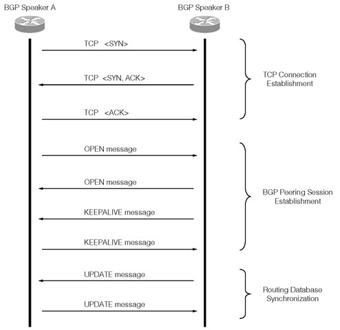
The BGP4+ routers cannot exchange any routing information until the peering process completes successfully. BGP defines a Finite State Machine (FSM) to represent its operation. Associated with the FSM is a set of events and timers that trigger state transition. The BGP peering process is part of the FSM but we omit the discussion of the BGP FSM in detail. Instead, we will describe the peering process through one possible scenario as illustrated in Figure 1-17.
The peering process begins by first establishing a TCP connection. One BGP4+ router initiates the TCP connection to another BGP4+ router. It is possible that both routers try to initiate the TCP connection to each other at the same time. In order to avoid establishing two TCP connections, the BGP router with the smaller BGP Identifier (see Figure 1-19) will cancel its TCP connection request. The OPEN message is the first BGP message sent once the underlying TCP connection has been established successfully. A subsequent KEEPALIVE message confirms the OPEN message. Notice two BGP speakers send the OPEN and the KEEPALIVE messages. The BGP speakers then exchange their routing databases through the UPDATE message once the BGP peering session is established.
FIGURE 1-17
For each of its peers, a BGP router maintains a database that stores the routes advertised by its peer, and a separate database that stores the routes that it advertised to the peer. By maintaining separate databases on incoming and outgoing route exchanges, each BGP router is able to determine which updated routes affect its peer, and distributes to its peer only those updates to reduce routing traffic.
Since BGP is mainly deployed between different ISPs or between different companies, routing policies and enforcement of those policies play a significant role in BGP It is important for an ISP or a company to define what types of routes can be accepted from a peer, what types of routes can be distributed to a peer, what external routes can be redistributed internally and externally, which entry points inbound traffic should take, which exit points outbound traffic should take, and much more.
The following points summarize the key characteristics of the BGP4+ routing protocol:
• The routing algorithm selects a best route for each possible destination by examining the path information in conjunction with the locally administered routing policies.
• Routes are re-advertised to other routers that are not directly connected. There is no dynamic discovery of neighboring routers. Routes are exchanged with configured peer routers.
• Each piece of routing information consists of the destination, a gateway and the entire path to the destination.
• Distribution of routing information is reliable because route exchanges are carried over TCP.
• Origin of each route can be identified.
• Routing loops can be easily detected and avoided.
• Route computation is distributed in that selection decision made at one router depends largely on the route selection decisions made by other routers; however, decision of route selection can be made by local policy with a good degree of flexibility due to the explicit loop avoidance mechanism.
BGP4+ Messages
There are four message types in BGP, which are shown in Table 1-1. Message Header
The BGP message header format is shown in Figure 1-18. Marker This 4-byte field must be filled with all ones.
Length This 2-byte field specifies the size of the BGP message. The message header is 19 bytes, so Length can have the minimum value of 19. The maximum value that Length can have is 4096 including the header size.
Type This 1-byte field specifies the BGP message type as described in Table 1-1.
TABLE 1-1
|
Type |
Name |
Description |
|
1 |
OPEN |
The OPEN message is the first message that is sent over the TCP connection to initiate the peering exchange. |
|
2 |
UPDATE |
The UPDATE message carries routing information and is exchanged between the peers. A router also sends the UPDATE message to withdraw a previously advertised route. |
|
3 |
NOTIFICATION |
A router sends the NOTIFICATION message when it detects an error condition and closes the connection. |
|
4 |
KEEPALIVE |
Instead of relying on the TCP keep-alive mechanism, a BGP4+ router sends the KEEPALIVE message to detect the liveliness of its peer. The KEEPALIVE message is also sent in response to an OPEN message to complete the initial peering handshake. |
FIGURE 1-18
OPEN message
The OPEN message is the first message that is exchanged between two BGP speakers once the TCP connection is established between them. The OPEN message serves as the request to establish a peering relation. The OPEN messages also allow the BGP speakers to identify each other’s capabilities. The BGP speakers may fail to establish the peering relationship if incompatibilities are found.
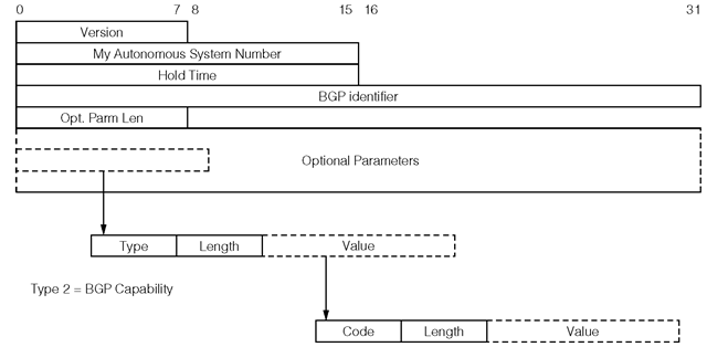
The OPEN message contains the message header and the additional fields that are shown in Figure 1-19.
Version This 1-byte field specifies the BGP protocol version number. The current BGP version is 4.
My Autonomous System Number This 2-byte field contains the ASN of the sender of the OPEN message.
Hold Time This 2-byte field specifies the maximum duration between successive KEEPALIVE or UPDATE messages. This value is proposed from the sender. The receiver sets its Hold
FIGURE 1-10
Time to be the smaller of its configured value and the proposed Hold Time from the received OPEN message. A zero Hold Time implies the sender does not need to send any message. The Hold Time must be at least 3 seconds if its value is not zero. In this case the TCP connection is closed if the receiver does not receive a KEEPALIVE, UPDATE or NOTIFICATION message when the Hold Time expires. The value received in the Hold Time field may cause a BGP speaker to reject the peering request.
BGP Identifier The 4-byte field contains a valid IPv4 unicast address of the sender.
Optional Parameters Length This 1-byte field specifies size of the optional parameters that are present in the message. No options are present if the length is zero. Otherwise these optional parameters will be negotiated with the receiver.
Optional Parameters The variable length Optional Parameters field contains the parameters to be negotiated with the receiver. Each optional parameter has the <type, length, value> format. The Type 2 parameter represents the BGP capabilities. The value field of a Type 2 parameter is encoded as <code, length, value>. Table 1-2 lists the currently defined capability codes, their descriptions and the documents in which they are defined.
KEEPALIVE message
The KEEPALIVE message contains only the message header and is therefore 19 bytes in size. The KEEPALIVE message is sent to avoid the expiration of the Hold Time and serves the same purpose as the TCP keepalive packets, that is, to verify the connection state. The KEEPALIVE message is rate limited and more than one message per second must not be sent. The KEEPALIVE message must not be sent if the negotiated Hold Time is zero.
TABLE 1-2
|
Value |
Description |
Reference |
|
0 |
Reserved |
[RFC3392] |
|
1 |
Multiprotocol Extensions for BGP-4 |
[RFC2858] |
|
2 |
Route Refresh Capability for BGP-4 |
[RFC2918] |
|
3 |
Cooperative Route Filtering Capability |
[ROUTE-FILTER] |
|
4 |
Multiple routes to a destination capability |
[RFC3107] |
|
5-63 |
Unassigned |
|
|
64 |
Graceful Restart Capability |
[IDR-RESTART] |
|
65 |
Support for 4-byte AS number capability |
[AS4BYTES] |
|
66 |
Deprecated (2003-03-06) |
|
|
67 |
Support for Dynamic Capability (capability specific) |
|
|
68-127 |
Unassigned |
|
|
128-255 |
Vendor Specific |
FIGURE 1-20


