Ray Casting
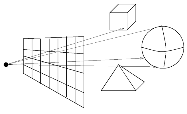
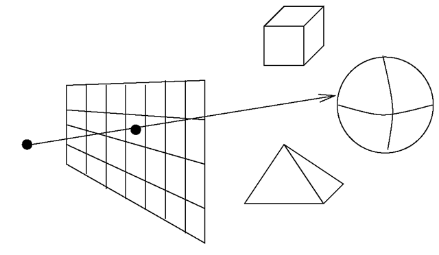
Ray casting is another image-precision technique for visible surface determination. For each pixel in the clipping rectangles of the projection plane a ray parallel to the direction of projection is cast. The ray should start at the front clipping plane and end at the back clipping plane. The first object that the ray meets determines the colour of the pixel. Ray casting is suitable for parallel projection as well as perspective projection without an additional transformation that turns the perspective projection into a parallel projection. The rays are parallel to the direction of projection for a parallel projection and for a perspective projection the rays are cast along the connections between the centre of projection and the pixels. Figure 7.7 illustrates the ray casting technique. Pixels correspond to the centres of the centres of the squares of the projection plane in the figure.
For a perspective projection with its centre of projection in the point (x0,y0,z0), the ray to the pixel with the coordinates (x\,y\,z\) can be parameterised by
Fig. 7.7 Ray casting
where
For values t < 0 the ray is behind the centre of projection, for t e [0,1] between the centre of projection and the projection plane, and for t > 1 it is behind the projection plane.
In order to determine whether the ray intersects a polygon and, if yes, where it meets the polygon, the intersection point of the ray with the plane Ax + By + Cz + D = 0 induced by the polygon is calculated. Afterwards a test is carried out, yielding whether the intersection point lies within the polygon.
Inserting the ray (7.3) into the equation for the plane, one obtains for t the solution
Given that the equation Ax + By + Cz + D = 0 describes a plane, i.e., at least one of the coefficients A, B, C is nonzero, the denominator can become zero if and only if the ray is parallel to the plane. In this case, the plane is not important for the projection to the considered pixel.
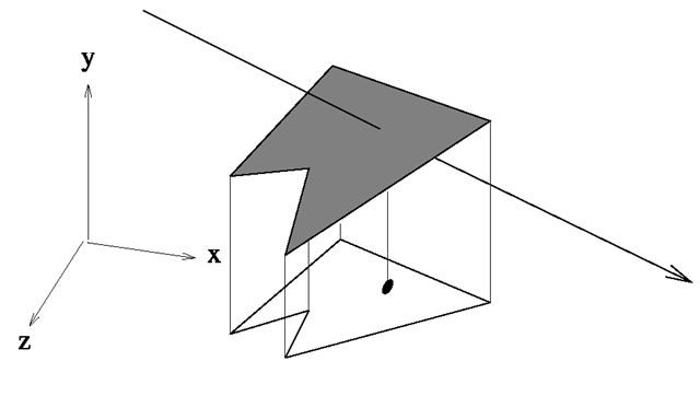
In order to determine whether the intersection point lies within the polygon, the polygon is projected together with the intersection point to one of the planes defined by the axes of the coordinate system. This means that one of the coordinates is set to zero. To avoid problems with roundoff errors, the plane that should be chosen for projection should be the one that is most parallel to the plane of the polygon. This means that the normal vector to the polygon plane and the normal vector to the projection plane should be as parallel as possible. The angle between these two normal vectors should be close to 0° or 180°. In other words, their dot product should either be close to one or -1 given that the normal vectors are normalised. The dot product of the normal vector (A,B,C) with a normal vector to a plane defined by two coordinate axes is simply the component of (A, B,C) that will be set to zero for the projection. Therefore, the projection plane is chosen orthogonal to the component which has the greatest absolute value in (A, B,C). After the projection, the odd parity rule is applied to decide whether the intersection point lies within the projected polygon as is illustrated in Fig. 7.8.
Fig. 7.8 Projection of a polygon to decide whether a point lies within the polygon
Coherence should be taken into account for ray casting in order to reduce the computational complexity. Coherence refers to exploiting considerations like the following ones:
• Neighbouring pixels usually obtain their colour from the same polygon.
• Once a ray intersects a polygon, it is not necessary to calculate intersections with polygons which are farther away.
Without exploiting coherence, 1000 · 1000 · 100, i.e., 100 million intersection tests would have to be carried out for a resolution of 1000 x 1000 pixels and 100 objects in the scene. Coherence can, for instance, reduce the computation time in the following way. When the polygon has been computed which determines the colour of a pixel, the intersection test for the neighbouring pixels should be applied first to this polygon. When the new ray intersects this polygon as well—and the chance is quite high—no intersection tests with polygons farther away are required anymore.
Ray casting can lead to aliasing effects when the back clipping plane is very far away. The background is composed of more or less randomly intersected objects in the far distance so that neighbouring pixels representing the background might not have the same or a similar colour. To avoid this effect, supersampling can be applied. For one pixel more than one ray is cast as shown in Fig. 7.9. The colour of the pixel is calculated as the mean or weighted mean of the corresponding colours obtained from the objects that the rays meet.
The computational effort will increase only slightly in this case since most of the additional rays can be used for more than one pixel. In Fig. 7.9 where four rays are cast for each pixel in an m x n pixel matrix, only (m + 1) · (n + 1) different rays instead of m · n without supersampling have to be computed. The additional effort is
For a resolution of 1000 x 1000 pixels the computational costs increase by approximately 0.2%.
Fig. 7.9 Super sampling
Priority Algorithms
The order in which objects are projected is not important at all for the z-buffer algorithm. By taking the information in the z-buffer into account, it can be guaranteed that objects which are farther away from the viewer will not overwrite closer objects, even if a distant object is projected later. The aim of priority algorithms is to find a suitable order in which objects can be projected so that no conflicts occur during the projection. This means that the distant objects have to be projected first and the closer objects later on. This would also guarantee that the projection of a distant object cannot overwrite a closer object. If a suitable order of projection can be found for the objects, there is no need for a z-buffer. The order of projection is also independent of the resolution so that priority algorithms belong to the class of object-precision techniques.
In the following, two objects, i.e., two polygons P and Q, are considered. The aim is to find out whether the order in which the polygons are projected is important. In other words, does one polygon hide at least parts of the other from view? It should be made sure that in such case the polygon closer to the viewer is projected after the other one. If there is no overlap of the z-coordinates of the two polygons, then the one with larger z-coordinates, the more distant one, is projected first. If the z-coordinates overlap, further tests have to be carried out.
In order to check whether the polygons overlap in the z-coordinate, it is sufficient to compare the z-components of their vertices. If the z-components of all vertices of one polygon are smaller than the z-components of all vertices of the other polygon, then there is no overlap in the z-coordinates.
If the x- or the y-coordinates of the polygons P and Q do not overlap, then the order of projection is not important for these polygons since their projections will be next to each other, as can be seen in Fig. 7.10 and neither of the two can hide the other from view. The test whether the x – or the y-coordinates do not overlap, can be carried out in the same way as for the z-coordinate.
If there are overlaps in all coordinates, the next test to be carried out is whether one polygon lies completely in front of or behind the plane that is induced by the other polygon. These two possibilities are illustrated in Fig. 7.11. In the left-hand side of the figure, the polygon should be projected first which lies behind the plane induced by the other. In the right-hand side of the figure, the polygon that lies completely in front of the plane induced by the other should be projected later.
Fig. 7.10 No overlap in the x-coordinate (left) or the y-coordinate (right)
Fig.7.11 Does one polygon lie completely in front or behind the plane induced by the other?
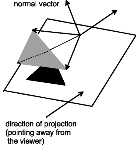
These two cases can be checked based on correctly oriented normal vectors. As an example, only the case in the right-hand side of Fig. 7.11 will be explained in detail. The normal vector to the plane induced by the polygon is the same normal vector as for the polygon itself. The normal vector must point to the viewer and not away from him. Otherwise, the polygon had been removed before by back-face culling. An arbitrary point in the plane is chosen and the vectors connecting the point in the plane with the vertices of the other polygon are considered. If the one polygon lies completely in front of the other polygon, then all these vectors must have an angle of less than 90° with the normal vector to the plane. This is the case if and only if the dot product of each of these vectors with the normal vector to the plane is positive. Figure 7.12 illustrates this fact. The angles between the normal vector to the plane and the vectors to the vertices of the other polygon are all smaller than 90°.
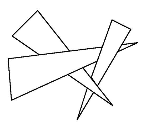
Unfortunately, these criteria are not always sufficient to determine a suitable order of projection for the objects. There are cases as in Fig. 7.13 where it is impossible to achieve a correct image by any order of projection. If none of the above criteria is applicable, it is necessary for the priority algorithm to further subdivide the polygons participating in the conflict in order to find a correct order of projection. Even if such cases will not happen very often, it is not easy to determine a suitable subdivision of the corresponding polygons.
Fig. 7.12 Determining whether a polygon lies completely in front of the plane induced by the other polygon
Fig. 7.13 A case where no correct order exists in which the polygons should be projected
![tmpc009-412_thumb[2]_thumb tmpc009-412_thumb[2]_thumb](http://what-when-how.com/wp-content/uploads/2012/06/tmpc009412_thumb2_thumb_thumb.png)
![tmpc009-413_thumb[2]_thumb tmpc009-413_thumb[2]_thumb](http://what-when-how.com/wp-content/uploads/2012/06/tmpc009413_thumb2_thumb_thumb.png)
![tmpc009-415_thumb[2]_thumb tmpc009-415_thumb[2]_thumb](http://what-when-how.com/wp-content/uploads/2012/06/tmpc009415_thumb2_thumb_thumb.png)
