Geometric Transformations
In addition to geometric objects, geometric transformations play a crucial role in computer graphics. Geometric transformations can be used to position objects, i.e., to shift them to another position or to rotate them, to change the shape of objects, for instance to stretch or shrink them in one direction, or to move objects or change the shape of objects step by step in animated scenes.
Before discussing geometric transformations in more detail, it is necessary to explain some general conventions. In computer graphics, points as well as vectors are used. From a purely mathematical point of view, both can be represented as elements of the space Rn, i.e., as a tuple of real numbers. Especially in physics, it is very important to distinguish clearly between these two concepts of points and vectors. In the framework of this topic and from the viewpoint of computer graphics, it is very common to switch between the interpretations of a tuple of real numbers as a point and as a vector, giving more flexibility in handling certain matters. A tuple (x1,…,xn) e Rn might occur in one equation as a point and in the next equation it might be interpreted as a vector. Hopefully, physicists will tolerate the abuse of notation in the context of this topic. For equations within this topic, column vectors will be used consistently. Within the text, points are sometimes written as row vectors in order to avoid stretching of text lines. In those cases where a point is explicitly understood as a column vector, the symbol for transposing vectors will be used, i.e., the point will be written as (x, y)T e R2 and (x,y,z)T e R3, respectively.
The dot product of two vectors u and v will be denoted in the following way, which is also very common in statistics:
The most important geometric transformations are scaling, rotation, shearing and translation.
A scaling leads to stretching or shrinking of objects in the direction of the x- and the y-axis. A scaling S(sx,sy) maps the point (x, y) to the point (x ‘ ,y’) given by
sx is the scaling factor in the direction of the x-axis. If |sx | > 1 holds, then a stretching in the direction of the x-axis is carried out. For |sx | < 1 shrinking takes place. If sx is negative, in addition to stretching or shrinking in the x-direction, a reflection with respect to the y-axis is applied. In the same way, sy leads to stretching or shrinking in the direction of the y-axis and a negative value of sy incorporates an additional reflection with respect to the x-axis.
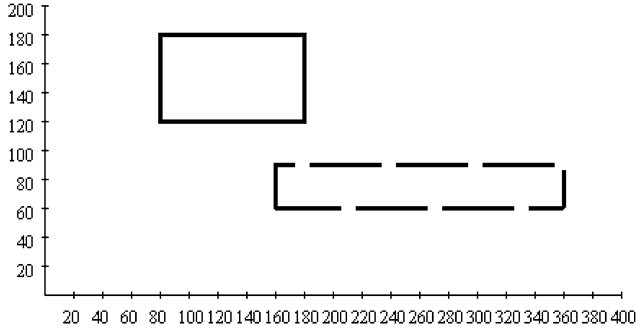
Applying a scaling to an object means that the scaling is carried out pointwise. The same holds for all other geometric transformations. They carry out pointwise transformations of objects. As an example, the translation with the scaling factors sx = 2 and sy = 0.5 is considered, stretching along the x-axis by the factor 2 and shrinking in the direction of the y-axis by the factor 0.5. The application of this scaling to the rectangle whose lower left corner is located at the point (80, 120) and whose upper right corner is at (180, 180) yields a rectangle whose width has doubled with half the original height. But in addition, the centre of the rectangle is also transformed so that the transformed rectangle is shifted to the lower right compared to the original rectangle. Figure 2.134 shows the original rectangle and the rectangle after scaling by dashed lines. A scaling is always carried out with respect to the origin of the coordinate system. Applying a scaling to an object that is not centred around the origin of the coordinate system will lead to a translation of the (centre of the) object in addition to the scaling.
Another important group of geometric transformations are rotations that are determined by a single parameter, the rotation angle. The rotation is carried out anticlockwise around the origin of the coordinate system in case of a positive angle. A negative angle means that the rotation is carried out in a clockwise manner. The rotation Κ(θ) by the angle θ maps the point (x, y) to the point (x’,y’) given by
Fig. 2.13 Scaling applied to a rectangle
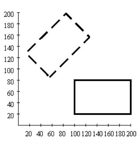
Fig. 2.14 A rotation applied to a rectangle
A rotation is always carried out around the origin of the coordinate system. Therefore, a similar shifting effect as in the case of scalings happens, when an object is not centred around the origin. In Fig. 2.14 a rotation by an angle of 45° was carried out, mapping the original rectangle to the rectangle drawn with dashed lines.
The shear transformation is another elementary geometric transformation that causes a certain deformation of objects. Similar to scalings, the shear transformation requires two parameters, however, not on the main diagonal of the transformation matrix, but on the other two positions. Applying a shear transformation Sh(sx,sy) to a point (x, y) yields the point (x’ ,y’) with the new coordinates
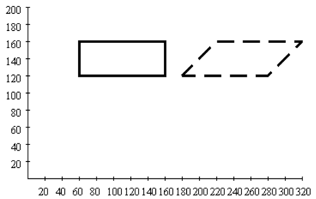
As in the case of scalings and rotations, shear transformations are carried out with respect to the origin of the coordinate system, so that an object that is not centred around the origin will not only be deformed by a shear transformation, but also shifted. The dashed rectangle is obtained from the original rectangle in Fig. 2.15 by applying a shear transformation with the parameters sx = 1 and sy = 0.
Fig. 2.15 A shear transformation applied to a rectangle
Since sy = 0 was chosen for this shear transformation, the shearing takes place in the direction of the y -axis. When the shearing should be carried out in the direction of the x-axis, sx = 0 must hold.
The last elementary or primitive geometric transformation to be considered here is very simple, but differs from the other three types of elementary transformation that were introduced so far in an important aspect. A translation T(dx,dy) causes a shift by the vector d = (dx,dy)T. This means the translation maps the point (x, y) to the point
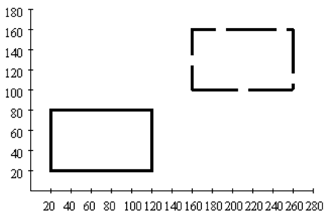
In Fig. 2.16 a translation defined by the vector d = (140, 80)T is applied to a rectangle, mapping it to the dashed rectangle.
In contrast to the other transformations introduced so far, translations are not linear, so that they cannot be represented in terms of matrix multiplication. A matrix multiplication will always leave the zero vector unchanged, whereas a translation will shift all points including the origin of the coordinate system corresponding to the zero vector. Translations are affine, but not linear mappings.
Within computer graphics, more complex transformations are usually described or generated as compositions of elementary geometric transformations. A transformation composed of scalings, rotations and shear transformations can be specified by a single matrix, obtained as the product of the matrices encoding the corresponding elementary transformations. When also translations are involved, the composition of transformation can no longer be computed by simple matrix multiplication and represented by a single matrix. If all this was possible within matrix calculus, this would be a great advantage in terms of memory—just a single matrix is required to represent a complex transformations—and in terms of computational efficiency since all that would be needed for fast computations are efficient implementations of matrix operations.
Fig. 2.16 Translation of a rectangle
In order to represent also translations in matrix form, another representation of the coordinates of points is introduced. The next section will discuss this alternative representation called homogeneous coordinates in more detail.
Homogeneous Coordinates
This section introduces the representation of points in the two-dimensional plane in homogeneous coordinates. The same concept will also be applied later on to points in the three-dimensional space for the same reason, to allow the representation of 3D translations in matrix form. Homogeneous coordinates use an additional dimension for the representation of points. The point (x,y,z) in homogeneous coordinates is identified with the point (Z, Z) in Cartesian coordinates. The z-component of a point in homogeneous coordinates must not be zero. When the point (x0, y0) in Cartesian coordinates has to be transformed into homogeneous coordinates, the representation (x0, y0, 1) can be used. This is, however, not the only way to represent the point (x0, y0 ) in homogeneous coordinates. Any representation of the form (z · x0 ,z· y0 ,z) where z = 0 encodes also the same point. The points {(x,y,z) G R3 | (x,y,z) = (z · x0 ,z · y0, z)} lie on a line in the space R3 passing through the origin of the coordinate system. The line is given by the system of equations
Any point on this line, except the origin of the coordinate system, is a representative in homogeneous coordinates of the point (x0, y0) in Cartesian coordinates. Fixing a value for z for the representation in homogeneous coordinates, for instance z = 1, the Cartesian x/y-plane is represented by a parallel plane with the corresponding constant z-value.
Fig. 2.17 Homogeneous coordinates
Table 2.1 Elementary transformations in homogeneous coordinates
|
Transformation |
Notation |
Matrix |
|
translation |
T(dx,dy) |
 |
|
scaling |
S(sx,sy) |
 |
|
rotation |
R(O) |
 |
|
shear transformation |
S(sx,sy) |
 |
Figure 2.17 illustrates these relations. All points on the line shown in Fig. 2.17 represent the same point in the two-dimensional Cartesian plane R2. Choosing a constant value for z, for instance one of the planes shown in Fig. 2.17, the corresponding plane is a homogeneous representative of the Cartesian plane R2.
The origin of the Cartesian coordinate system corresponds to any point of the form (0,0,z) (z = 0) in homogeneous coordinates. This point is no longer a necessary fixed point of a linear mapping in terms of homogeneous coordinates, i.e., a linear mapping from R3 to R3. The linear mapping can map this point to another point in homogeneous coordinates.
In homogeneous coordinates a translation can now be written as matrix multiplication:
The other elementary transformation can be extended to homogeneous coordinates in a straightforward manner, leading to the set of transformation matrices shown in Table 2.1.
Rotations and translations preserve lengths and angles. Scalings and shear transformations do not preserve lengths and angles in general, but at least parallel lines will be mapped to parallel lines again.
Fig. 2.18 Differing results on changing the order for the application of a translation and a rotation
With this matrix representation in homogeneous coordinates, the composition of geometric transformations can be computed by matrix multiplication.
All matrices, introduced for the elementary geometric transformations are of the form
It is easy to verify that the product of two such matrices results again in a matrix of the same form. Therefore, geometric transformations are usually represented and stored in this way in computer graphics. This does not only apply to transformations that operate on the two-dimensional plane, but also to transformations in the three-dimensional space that will be discussed in Chap. 5. It is now obvious that a graphics card of a computer must—among other things—be able to carry out matrix operations as fast as possible.
For the composition of transformations it should be taken into account that the order in which the transformations are applied is of importance. Matrix multiplication is a noncommutative operation. The right part of Fig. 2.18 shows the different results that are obtained, when the order in which translation and rotation are applied is changed. When first a translation with the translation vector (40, 20)T and afterwards a rotation by 45° is applied, then the rectangle on the left-hand side of Fig. 2.18 is mapped to the upper rectangle on the right. When the rotation is carried out first and afterwards the translation, the result is the lower right rectangle. This effect occurs in general in all cases, when geometric transformations of different types are combined. Only when transformations of the same type, i.e., only rotations, only translations, only scalings or only shear transformations, are composed, the order in which the transformations are applied is of no importance.
It should also be taken into account that transformations in matrix notation or as compositions of mappings are carried out from right to left. The transformation
or in matrix notation
means that first the rotation R(O) and then the translation T(dx,dy) is applied to the point v.
![tmpc009-23_thumb[2][2] tmpc009-23_thumb[2][2]](http://what-when-how.com/wp-content/uploads/2012/06/tmpc00923_thumb22_thumb.png)
![tmpc009-24_thumb[2][2] tmpc009-24_thumb[2][2]](http://what-when-how.com/wp-content/uploads/2012/06/tmpc00924_thumb22_thumb.png)
![tmpc009-25_thumb[2][2] tmpc009-25_thumb[2][2]](http://what-when-how.com/wp-content/uploads/2012/06/tmpc00925_thumb22_thumb.png)


![tmpc009-28_thumb[2][2] tmpc009-28_thumb[2][2]](http://what-when-how.com/wp-content/uploads/2012/06/tmpc00928_thumb22_thumb.png)

![tmpc009-30_thumb[2][2] tmpc009-30_thumb[2][2]](http://what-when-how.com/wp-content/uploads/2012/06/tmpc00930_thumb22_thumb.png)

![tmpc009-32_thumb[2][2] tmpc009-32_thumb[2][2]](http://what-when-how.com/wp-content/uploads/2012/06/tmpc00932_thumb22_thumb.png)

![tmpc009-38_thumb[2][2] tmpc009-38_thumb[2][2]](http://what-when-how.com/wp-content/uploads/2012/06/tmpc00938_thumb22_thumb.png)

![tmpc009-40_thumb[2][2] tmpc009-40_thumb[2][2]](http://what-when-how.com/wp-content/uploads/2012/06/tmpc00940_thumb22_thumb.png)
![tmpc009-41_thumb[2][2] tmpc009-41_thumb[2][2]](http://what-when-how.com/wp-content/uploads/2012/06/tmpc00941_thumb22_thumb.png)
![tmpc009-42_thumb[2][2] tmpc009-42_thumb[2][2]](http://what-when-how.com/wp-content/uploads/2012/06/tmpc00942_thumb22_thumb.png)
