Introduction
Reconfigurable computing is breaking down the barrier between hardware and software design technologies. The segregation between the two has become more and more fuzzy because reconfigurable computing has now made it possible for hardware to be programmed and software to be synthesized. Reconfigurable computing can also be viewed as a trade-off between general-purpose computing and application specific design. Given the architecture and design flexibility, reconfigurable computing has catalyzed the progress in hardware-software codesign technology and a vast number of application areas such as scientific computing, biological computing, artificial intelligence, signal processing, security computing, and control-oriented design, to name a few.
In this article, we briefly introduce why and what is reconfigurable computing in the introduction section. Then, the resulting enhancements of hardware-software codesign methods and the techniques, tools, platforms, design and verification methodologies of reconfigurable computing will be introduced in the background section. Furthermore, we will introduce and compare some reconfigurable computing architectures. Finally, the future trends and conclusions will also be given. This article is aimed at widespread audiences, including both a person not particularly well grounded in computer architecture and a technical person.
Why Reconfigurable Computing?
With the popularization of the use of computers, computer-aided computing can be roughly divided into two technical areas, one of which is general-purpose computing and the other is application-specific integrated circuit (ASIC) computing.
On one extreme, general-purpose computing was accomplished by the world’s first fully operational electronic general-purpose computer, called Electronic Numerical Integrator and Calculator (ENIAC), built by J. Presper Eckert and John Mauchly. But it is well-known as von Neumann computer because ENIAC was improved by John von Neumann (Hennessy & Patterson, 2007). A general-purpose computer is a single common piece of silicon, called a microprocessor, that could be programmed to solve any computing task. This means many applications could share commodity economics for the production of a single integrated circuit (IC). This computing architecture has the flexibility and superiority that the original builders of the IC never conceived (Tanner Research, 2007).
On the other extreme, an ASIC is an IC specifically designed to provide unique functions. ASIC chips can replace general-purpose commercial logic chips, and integrate several functions or logic control blocks into one single chip, lowering manufacturing cost and simplifying circuit board design. Although the ASIC has the high performance and low power advantages, its fixed resource and algorithm architecture result in drawbacks such as high cost and poor flexibility.
As a tradeoff between the two extreme characteristics, reconfigurable computing has combined the advantages of both general-purpose computing and ASIC computing. A comparison among the different architecture characteristics is illustrated in Table 1 (Tredennick, 1996; Tessier & Burleson, 2001).
From Table 1, we observe that reconfigurable computing has the advantage of programmable or configurable computing resources, called configware (TU Kaiserslautern, 2007a), as well as configurable algorithms, called flowware (Hartenstein, 2006; TU Kaiserslautern, 2007b). Further, the performance of reconfigurable systems is better than general-purpose systems and the cost is smaller than that of ASICs. The main advantage of reconfigurable system is its high flexibility, while its main disadvantage is its high power consumption. The design effort in terms of nonrecurring engineering (NRE) cost is between that of general-purpose processor and ASICs.
Because reconfigurations of underlying resources help achieve the goals of balance among performance, cost, power, flexibility, and design effort. The reconfigurable computing architecture has enhanced the performances of large variety of applications, including embedded systems, SoCs, digital signal processing, image processing, network security, bioinformatics, supercomputing, boolean SATisfiability (SAT), spacecrafts, and military applications. We can say that reconfigurable computing will widely, pervasively, and gradually impact human lives.
Table 1. Comparison of representative computing architecture
| Computing Architecture | Programming source Resources Algorithms | Advantage
Design Performance Cost Power Flexibility effort (NRE) |
|||||
| General-purpose | Fixed | Software | Low | Low | Medium | High | Low |
| ASIC | Fixed | Fixed | High | High | Low | Low | High |
| Reconfigurable | Configware | Flowware | Medium | Medium | High | High | Medium |
What is Reconfigurable Computing?
In 1960, Estrin (1960) first proposed the term “reconfigurable computing.” The reconfigurable computing architecture is composed of a general-purpose processor and reconfigurable hardware logic. The reconfigurable computing architecture can be concisely defined as Hardware-On-DemandTM (Schewel, 1998), general purpose custom hardware (Goldstein et al., 2000) or a hybrid approach between ASICs and general-purpose processors (Singh et al. 2000).
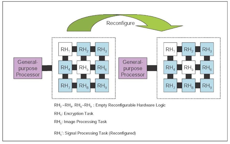
We illustrate a general reconfigurable computing architecture in Figure 1. In this architecture, the reconfigurable hardware logic executes application-specific computation intensive task, such as encryption (RH1) and image processing (RH5) as shown in Figure 1. The processor is used to control the behavior of the task running in the reconfigurable hardware and some other functions such as external communications. When a reconfigurable hardware has finished its computation, such as the encryption task in RH1, the processor reconfigures the hardware to execute another task such as the signal processing task. During this reconfiguration process, the image processing task continues to execute in RH5 without interruption.
Figure 1. Reconfigurable computing
From the above illustration, we can also define recon-figurable computing as a discipline in which system or application functions can be changed by configuring a fixed set of logic resources through memory settings (Hsiung & Santambrogio, 2008). Functions may be transforms, filters, codec, and protocol, the fixed set of logic resources may be logic block, I/O block, routing block, memory block, and application-specific block, and the memory settings mean configuration bits.
background
Materials science and technology progress has resulted in the maturity and development of reconfigurable computing. To understand the development of reconfigurable computing, an important perspective is to view it from the transition of hardware-software (HW-SW) codesign technology to reconfigurable computing. In the following, we will first introduce reconfiguration techniques and the Field-Programmable Gate Arrays (FPGA) (Gokhale & Graham, 2005). Furthermore, we will introduce some reconfiguration tools and platforms used in the academia and the industry. Finally, the design and verification methodologies will also be introduced.
From Codesign to Reconfiguration
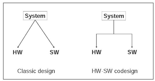
HW-SW codesign is an emerging topic that highlights a unified view of hardware and software (Vahid & Givargis, 2002). It is a system design methodology different from classic design, as illustrated in Figure 2.
The classic design partitions a system into hardware and software. Because a software designer may not know the final hardware architecture design and the hardware designer may also be unacquainted with the software design flow, hardware and software and are often implemented independently and then integrated toward the end of the design flow. If problems crop up during integration, changing either the hardware or the software could both be quite difficult. This will increase the maintenance difficulty and also delay the marketing time.
To address the problems mentioned above, a system design methodology called HW-SW codesign was proposed, which emphasizes the consistency and the integration between hardware and software. It is based on a system-level view, and thus eases both software verification and hardware error detection. The HW-SW codesign methodology reduces the cost of design and also shortens the time-to-market.
Nevertheless, the high cost in hardware design is a major issue of the HW-SW codesign flow because hardware must go through a time-consuming flow including design, debug, manufacturing, and test. The inconvenient hardware manufacturing forces designers to search for alternate ways. One way is to use modeling languages such as SystemC (Black & Donovan, 2004) to simulate hardware and software. Another method is to use concurrent process models to simulate hardware and software tasks. However, simulation speed is a major bottleneck (Schewel, 1998). To overcome the drawback, prototyping using reconfigurable architectures has become the most appropriate choice for HW-SW codesign. In contrast to ASIC design, reconfigurable hardware can be much easily used to design hardware prototypes that can be integrated with software to obtain performance and functional analysis results much more efficiently and accurately. We can thus say that reconfigurable computing has accelerated and enhanced the HW-SW codesign flow.
Figure 2. Classic design and HW-SW codesign
Reconfiguration Techniques
From the mid 1980s, reconfigurable computing has become a popular field due to the FPGA technology progress. An FPGA is a semiconductor device containing programmable logic components and programmable interconnects (Compton & Hauck, 2002) but no instruction fetch at run time, that is, FPGA do not have a program counter (Hartenstein, 2006). In most FPGAs, the logic components can be programmed to duplicate the functionality of basic logic gates or functional intellectual properties (IPs) and also include memory elements composed of simple flip-flops or more complete blocks of memories (Barr, 1998).
Besides FPGA, the reconfigurable data-path array (rDPA) is another reconfiguration technique. In contrast to FPGA having single bit programmable logic blocks, rDPAs have multiple bits wide (e.g., 32 bit path width) reconfigurable data-path units (rDPUs). An rDPA is structurally programmed from configware sources, compiled into pipe networks to be mapped onto the rDPA. The term reconfigurable data path array, or rDPA, had been proposed by Rainer Kress in 1993 at TU Kaiserslautern (Hartenstein, 2006). For further details on the comparison between FPGA and rDPA, readers can refer to the section on “Fine-grained vs. Coarse-grained Reconfiguration.”
The main part of a reconfigurable system is the con-figware such as FPGA or rDPA. Besides configware, the software is another essential part that can control and thus incorporate the configware into a reconfigurable system. Although configware can provide resources for high performance computation, complex control must be implemented in software. Reconfiguring hardware implies software must also be appropriately reconfigured, and thus we need recon-figurable software design too (Compton & Hauck, 2002; Voros & Masselos, 2005).
Reconfiguration Tools and Platforms
To construct a reconfigurable computing system, designers need computer-aided design (CAD) tools for system design and implementation, such as a design analysis tool for architecture design, a synthesis tool for hardware construction, a simulator for hardware behavior simulation, and a placement and routing tool for circuit layout. We may build these tools ourselves or we can also use commercial tools and platforms for reconfigurable system design, such as the Embedded Development Kit (EDK) from Xilinx, which is a common development tool. The EDK integrates both the software and the hardware components of a design to develop complete systems (Donato et al., 2005). In fact, EDK provides developers with a rich set of design tools, such as Xilinx Platform Studio (XPS), gcc, and Xilinx Synthesizer (XST). It also provides a wide selection of standard peripherals required to build systems with embedded processors, like MicroBlaze or IBM PowerPC (Xilinx, 2007). Besides Xilinx EDK, we list commonly used commercial FPGA and electronic design automation (EDA) tools in Table 2.
Table 2. Commercial reconfiguration tools
| Functionality | Tool Name | FPGA/EDA Company |
| Design Analysis | PlanAhead | Xilinx |
| FPGA Suite Tools | ISE Foundation Quartus
FPGA Advantage |
Xilinx Altera
Mentor Graphics |
| FPGA Synthesizer | Synplify Pro FPGA Compiler Leonardo Spectrum Precision Synthesis | Synplicity Synopsys Mentor Graphics Mentor Graphics |
| Simulator | ModelSim NC SIM
Scirocco Simulator Spexsim VCS Verilog-XL |
Mentor Graphics
Cadence Cadence Verisity Synopsys Cadence |
After designers build a reconfigurable system, a platform for operating and testing is needed. We can use the platforms developed in the industry or in the academia, such as the Caronte Architecture (Donato et al., 2005) and the Kress-Kung Machine (Hartenstein, 2006). The Caronte Architecuture is entirely implemented in the FPGA device and constituted by several elements such as a processor, memories, a set of reconfigurable devices and a reconfiguring device. It implements a module-based system approach based on an EDK system description and provides a low cost approach to the dynamic reconfiguration problem. The Kress-Kung is a data-stream-based machine. Instead of rDPAs, it has no Central Processing Unit (CPU) or program counter.
Design and Verification Methodologies
To design reconfigurable computing systems, we need some appreciation of the different costs and opportunities inherent in reconfigurable architectures. Currently, most systems are designed based on our past experiences. We can use the design patterns identified and cataloged by DeHone et al. (DeHon et al., 2004). Each pattern description has a name, intent, motivation, applicability, participants, consequences, implementation, known uses, and related patterns. They also cataloged the design patterns into several classification types, such as patterns for area-time tradeoffs and patterns for expressing parallelism. This classification is a good start for constructing reconfigurable systems. In the following, we present a typical design methodology and a typical verification methodology for illustration purpose.
Tseng and Hsiung (2005) proposed a UML-based design flow for Dynamically Reconfigurable Computing Systems (DRCS). This design flow is targeted at the execution speedup of functional algorithms in DRCS and at the reduction of the complexity and time-consuming efforts in designing DRCS. The most notable feature of the design flow is a HW-SW partitioning methodology based on the UML 2.0 sequence diagram, called Dynamic Bitstream Partitioning on Sequence Diagram (DBPSD). In DBPSD, partitioning guidelines are also included to help designers make prudent partitioning decisions at the class method granularity. The enhanced sequence diagram in UML 2.0 is capable of modeling complex control flows, and thus the partitioning can be done efficiently on the sequence diagrams.
After design and implementation, we need to verify that the system design is correct and complete. Correctness means that the design implements its specification accurately. Completeness means that our specification described appropriate output responses to all relevant input sequences (Vahid & Givargis, 2002).
Hsiung, Huang, and Liao (2006) proposed a SystemC-based performance evaluation framework, called Perfecto, for dynamically partially reconfigurable systems, which is an easy-to-use system-level framework. Perfecto is able to perform rapid explorations of different reconfiguration alternatives and to detect system performance bottlenecks. In their framework, a system designer can detect performance bottlenecks, functional errors, architecture defects, and other system faults at a very early design phase.
reconfiguration architectures
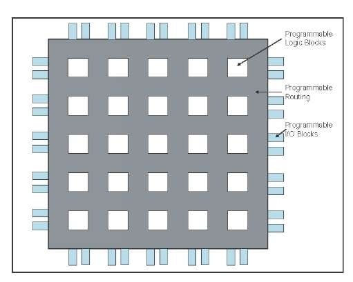
As illustrated in Figure 3, FPGA is constructed from a large number of programmable logic structures, called programmable logic blocks, which can be interconnected to each other through programmable routing resources. If we want to connect the programmable logic blocks to the external, we can also interconnect them to the programmable I/O blocks through the programmable routing resources (Gokhale & Graham, 2005).
The programmable logic block can be configured as the desired circuit functionality and the programmable I/O blocks can be configured for communicating with outer devices. Between programmable logic blocks or between programmable logic blocks and I/O blocks, programmable routing can be configured for interconnection (Gokhale & Graham, 2005).
In this section, we will go through different classification schemes of reconfigurable architectures. In terms of reconfiguration granularity, we have fine-grained and coarse-grained reconfiguration. If we consider the time when reconfigurations are performed, we have static and dynamic reconfigurations. Considering the amount of logic resources that can be reconfigured, we have full and partial reconfigurations. Considering the model of reconfiguration supported, we will introduce column-based and tile-based reconfiguration. Finally, we give a comparison among different reconfiguration architectures.
Figure 3. A generic FPGA architecture
Fine-Grained vs. Coarse-Grained Reconfiguration
To understand what fine-grained and coarse-grained mean, we can refer to Table 3 as formulated in Hartenstein (2006). In Table 3, the data path width indicates the granularity of the configware, that is, fine-grained or coarse-grained. The data path of FPGA is about 1 bit wide and rDPA is about 32 bits, so we call FPGA fine-grained and rDPA coarse-grained.
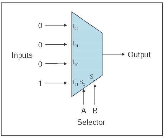
Besides the difference in data path width, the recon-figurable unit is also different. Fine-grained reconfiguration uses look-up table (LUT) as the typical reconfigurable unit and coarse-grained uses ALU-like unit. LUT is the most common implementation method for combinational logic. The characteristic of LUT is to use a multiplexer to select the input data. For example, a four inputs and one output multiplexer, denoted as a 4×1 multiplexer, is used as an LUT, which is shown in Figure 4.
In Figure 4, the selector will select which input will be connected to the output. For example, if the A=1 and B=0, the output port will be connected to input port I and output data is 0. For the example in Figure 4, the LUT represents a logic AND gate. When AB = “00″, “01″, “10″, “11″, the output will be connected to corresponded input I00, I01, I10,
I11 respectively, and result in “0″, “0″, “0″, “1″. These are the values in a logic AND truth table. Based on this characteristic, a LUT can reserve, that is, reconfigure, the input to obtain any logic circuit.
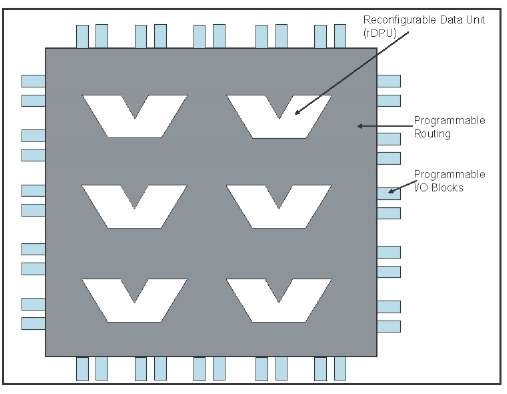
The rDPA is an array of reconfigurable data unit (rDPU) and can be illustrated as in Figure 5. A typical example of rDPU is an arithmetic-logic unit (ALU) which is found in a von Neumann computer. The ALU is a digital circuit that calculates arithmetic and logic operations. The rDPUs constitute the set of coarse-grained programmable logic blocks.
Figure 4. A two-input look-up table
Table 3. Comparison of reconfiguration granularities
| Fine-grained | Coarse-grained | |
| Configware | Field-programmable gate array (FPGA) | Reconfigurable data-path array (rDPA) |
| Data path width | ~ 1 bit | ~ 32 bits |
| Physical level of basic reconfigurable units | Gate level | RT level |
| Typical reconfigurable units examples | LUT (look-up table) | ALU-like |
| Configuration time | Milliseconds | Microseconds |
| Clock cycle time | ~ 0.5 GHz | ~1 – 3 GHz |
Figure 5. Reconfigurable data array
Static vs. Dynamic Reconfiguration
As we mentioned earlier, traditional configwares can be configured for a hardware design as required. If we want to replace a new hardware design in the configware, the configware needs to be sent the RESET signal for reconfiguration use. Because the reset action usually consumes a lot of time, we would want to reduce the number of times this action is taken. In other words, we can say that traditional config-wares are reconfigurable, but not run-time reconfigurable (Barr, 1998). We can classify these configwares as static reconfiguration unit.
Besides static reconfiguration, dynamic reconfiguration has also resulted from progress in new reconfiguration technologies. Run-time reconfiguration has added another dimension of flexibility in such systems. When we want to place a hardware design into a dynamically reconfigurable configware, we can just stop the clock of the region we need, reset the hardware resources in that region, and then configure the desired the hardware design and start the clock for this region. The other regions on this configware will still work unrestrictedly. Thus, it is called dynamic or run-time reconfiguration. Dynamic reconfiguration technique reduces the response time and the configuration overhead compared to static reconfiguration. Nowadays, industry products, such as Xilinx Virtex-II, Virtex-II Pro, Virtex-4, and later versions of the Virtex series all support dynamic reconfiguration.
Full vs. Partial Reconfiguration
In traditional reconfiguration, we integrate a set of one or more hardware design and configure them using a single reconfiguration action into a configware. We can call this type of reconfiguration as full reconfiguration. If a hardware design uses much fewer resources than that available in the configware, full reconfiguration will result in low resource utilization.
If the configware can be configured partially, resource utilization can be increased and portions of the chip can be reconfigured while other parts can still continue running and computing.
Partial reconfiguration is illustrated in Figure 6, where the resource usage of hardware design A is smaller than that available in the configware. The configware is partially configured with the bitstream of design A. When another hardware design B is required, the configware will again be partially configured with hardware design B. During the configuration of B, A will run without any glitches. Thus, the partial reconfiguration technology results inbetter configware resource utilization than that in full reconfiguration.
Currently, the dynamically reconfigurable architectures also support partial reconfiguration, including Xilinx Vir-tex-II, Virtex-II Pro, Virtex-4, and the later versions of the Virtex series.
Column-Based vs. Tile-Based Reconfiguration
Traditionally, configware was designed for column-based reconfiguration, that is, the basic unit of configuration is a column that crosses the chip. Thus, in implementing a partially reconfigurable system, the configware is modeled as a one-dimensional area of resources in which hardware designs can be configured. A typical example of configware with column-based reconfiguration is the Xilinx Virtex II series of FPGA chips. Tile-based reconfiguration is another more flexible architecture that can be found in the Xilinx Virtex 4 series of FPGA chips. These two types of reconfiguration are illustrated in Figure 7.
Figure 6. An example of partial reconfiguration
Figure 7. Column-based vs. tile-based reconfiguration
A tile is the area smaller than a column. In the Xilinx Virtex 4 series of FPGA chips, each column is partitioned into two tiles. Thus, designers can have the two-dimensional vision of their reconfigurable system. As shown in Figure 7, if the sizes of hardware designs A and B are the same in the column-based and the tile-based instances, then they can be configured with more flexibility with the tile-based one. The resource utilization of the configware is also increased with tile-based reconfiguration.
Reconfiguration Architecture comparisons
Summarizing and analyzing the discussions from above, we can compare the reconfiguration architectures as in Table 4, where the traditional reconfiguration architecture supports static and full reconfiguration, while the modern architecture supports dynamic and partial reconfiguration. When the resource requirements of a hardware design can be met by a configware, the performance and power will be the same for both traditional and modern reconfiguration architectures because dynamic and partial reconfiguration techniques are not needed. However, when a hardware design cannot fit in a configware, these modern techniques will be required, resulting in higher performance and power.
The cost, flexibility, and design effort are all quite high for the modern architecture because the dynamic and partial reconfiguration techniques require additional hardware support, tool support, scheduling support, and user expertise, while providing greater flexibility in system design.
future trends
With technology progress, not only has the gate count capacity of FPGA increased rapidly, but chip reconfiguration can now be performed at run-time and partially. On one hand, the large gate capacity enables several hardware tasks to run concurrently in a single FPGA chip, which could also interact with software tasks running on a microprocessor. On the other hand, the partial run-time reconfigurability allows a system to dynamically change some of its hardware functionalities such as in mobile networking, wearable computing, and networked embedded systems. The complexity in designing such systems drives the need for an operating system that not only manages software tasks and resources, but also manages hardware tasks and related FPGA resources.
Table 4. Comparison of configuration
 |
 |
Advantage | |||||
| Temporal | Spatial | Performance | Cost | Power | Flexibility | Design effort | |
| Traditional | Static | Full | Low | Low | Low | Low | Low |
| Modern | Dynamic | Partial | High/Low | High | High/Low | High | High |
As an important feature trend, in the design and implementation an operating system for reconfigurable systems (OS4RS), we need to complete the following tasks.
1. OS4RS architecture design, including services, components, abstractions, performance, and hardware support mechanism
2. OS4RS kernel design, including the main kernel, system call interfaces, device drivers, loader, partitioner, scheduler, process manager, memory manager, placer, and router
3. OS4RS loadable modules design, including power manager, virtual memory manager, and other drivers
4. Set up the experiment platform and related software and computer-aided design (CAD) toolchains.
conclusion
Reconfigurable computing has become an important field of research in the academia and the industry. Reconfigurable architecture requires changes in both computer architectures and software systems leading to many research topics. A reconfigurable system is composed of a standard processor and a set of reconfigurable hardware. The reconfigurable hardware executes application-specific computing intensive task and is reconfigured by the standard processor. Reconfigurable computing combines the advantages of both general-purpose and ASIC computing, including performance, cost, power, flexibility and design effort. Due to its reconfigurable hardware characteristics, reconfigurable computing has accelerated and enhanced the HW-SW codesign flow.
Reconfigurable computing architecture can be classified according to the granularity of configware. One is fine-grained and the other is coarse-grained. The most representative of fine-grained configware is FPGA and rDPA is the representative of coarse-grained configware. To increase flexibility of reconfiguration, configwares have been enhanced from static/ full reconfiguration to dynamic/partial reconfiguration.
To develop a reconfigurable system, we can use the design patterns collected by DeHone et al. ( 2004) as an initial solution. Several tools and platforms developed in the academia and in the industry support reconfigurable computing and thus will help us to implement reconfigurable systems easily and rapidly. When the reconfigurable system is implemented, we can use the verification methodologies to verify the system.
With technology progress, not only has the gate count capacity of FPGA increased rapidly, but chip reconfiguration can now be performed at run-time and partially. To design and implement an operating system for reconfigurable systems (OS4RS) will be an important future trend in reconfigurable computing.
KEY TERMS
Codesign: The meeting of objectives by exploiting the trade-offs between hardware and software in a system through their concurrent design.
Configware: Source programs for configuration like field-programmable gate arrays (FPGA) or reconfigurable data path array (rDPA).
Dynamic/Static Reconfiguration: A reconfiguration technology that allows resources in a configware to be programmed without/with resetting the configware.
Field-Programmable Gate Arrays (FPGA): A programmable integrated circuit and contains a set of gate array that is programmed in the field.
Flowware: A data-stream-based software. It is the counterpart of the traditional instruction-stream-based software.
Full/Partial Reconfiguration: A traditional/modern reconfiguration technology which forces all/partial resources of a configware to be programmed during each configuration.
Reconfigurable Data Path Array (rDPA): A programmable integrated circuit with coarse-grained granularity.
Reconfiguration: The process of physically altering the location or functionality of configwares with new ones.
System on Chip/SoC: A chip which is complete to constitute an entire system or major subsystem.
Wearable Computing: A small portable computer that is designed to be worn on the body during use.
