Wigner-Seitz Cells
Crystals have symmetrical properties. Therefore, a crystal can be described as an accumulation of "unit cells." In general, the smaller such a unit cell, i.e., the fewer atoms it contains, the simpler its description. The smallest possible cell is called a "primitive unit cell." Frequently, however, a larger, nonprimitive unit cell is used, which might have the advantage that the symmetry can be better recognized. Body-centered cubic and face-centered cubic are characteristic representatives of such "conventional" unit cells.9 The Wigner-Seitz cell is a special type of primitive unit cell that shows the cubic symmetry of the cubic cells. For its construction, one bisects the vectors from a given atom to its nearest neighbors and places a plane perpendicular to these vectors at the bisecting points. This is shown in Fig. 5.11 for the bcc lattice.
Figure 5.11. Wigner-Seitz cell for the body-centered cubic (bcc) structure.
In the fcc lattice, the atoms are arranged on the corners and faces of a cube, which is equivalent to the center points of the edges and the center of the cell (Fig. 5.12). The Wigner-Seitz cell for this structure is shown in Fig. 5.13.
Figure 5.12. Conventional unit cell of the fcc structure. In the cell which is marked black, the atoms are situated on the corners and faces of the cubes. In the white cell, the atoms are at the centers of the edges and the center of the cell.
Figure 5.13. Wigner-Seitz cell for the fcc structure. It is constructed from the white cell which is marked in Fig. 5.12.
Translation Vectors and the Reciprocal Lattice
In Fig. 5.14(a) the fundamental vectors t1, t2, t3 are inserted in a unit cell of a cubic primitive lattice. By combination of these "primitive vectors" a translation vector,can be defined.
Figure 5.14. (a) Fundamental lattice vectors t1, t2, t3 in a cubic primitive lattice. (b) Fundamental lattice vectors in a conventional (white) and primitive, noncubic unit cell (black) of a bcc lattice. The axes of the primitive (noncubic) unit cell form angles of 109° 280.
Using this translation vector it is possible to reach, from a given lattice point, any other equivalent lattice point. For this, the factors n1, n2, n3 have to be integers. In Fig. 5.14(b) the fundamental vectors t1, t2, t3 are shown in a conventional unit cell of a bcc lattice.
Similarly, as above, we now introduce for the reciprocal lattice three vectors, b1, b2, b3, and a translation vector
where h1, h2, and h3 are, again, integers. (The factor 2p is introduced for convenience. In X-ray crystallography, this factor is omitted.)
The real and reciprocal lattices are related by a definition which states that the scalar product of the vectors t1 and b1 should be unity, whereas the scalar products of b1 and t2 or b1 and t3 are zero:
Equivalent equations are defined for b2 and b3. These nine equations can be combined by using the Kronecker-Delta symbol,
where dnm = 1 for n = m and dnm = 0 for n = m. Equation (5.17) is from now on our definition for the three vectors bn, which are reciprocal to the vectors tm. From (5.15) and (5.16) it follows10 that b1 is perpendicular to t2 and to t3, which means that t2 and t3 form a plane perpendicular to the vector b1 (Fig. 5.15). We therefore write11
Figure 5.15. Plane formed by t2 and t3 with perpendicular vector b1.
To evaluate the constant, we form the scalar product of ti and bi (5.18) and make use of (5.14):
This yields
Combining (5.18) with (5.20) gives
Equivalent equations can be obtained for b2 and b3:
Equations (5.21)-(5.23) are the transformation equations which express the fundamental vectors b1, b2, and b3 of the reciprocal lattice in terms of real lattice vectors.
As an example of how these transformations are performed, we calculate now the reciprocal lattice of a bcc crystal. The real crystal may have the lattice constant "a." We express the lattice vectors t1, t2, t3 in terms of the unit vectors, i, j, l in the x, y, z coordinate system (see Fig. 5.14(b)):
or, abbreviated,
and
To calculate b1, using (5.21), we form at first the vector product
and the scalar13 product
Combining (5.21) with (5.28) and (5.29) yields
or
Similar calculations yield
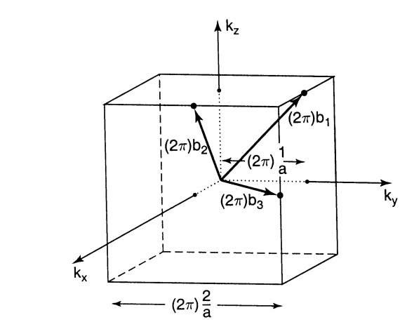
In Fig. 5.16, the vectors b1, b2, b3 are inserted into a cube of length 2/a. We note immediately an important result. The end points of the reciprocal lattice vectors of a bcc crystal are at the center of the edges of a cube. This means that points of the reciprocal lattice of the bcc structure are identical to the lattice points in a real lattice of the fcc structure, see Fig. 5.12. Conversely, the reciprocal lattice points of the fcc structure and the real lattice points of the bcc structure are identical.
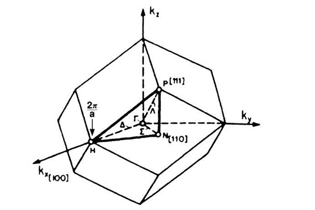
In Section 5.2, we constructed two-dimensional Brillouin zones by drawing perpendicular bisectors on the shortest lattice vectors. Similarly, a three-dimensional Brillouin zone can be obtained by bisecting all lattice vectors b and placing planes perpendicular on these points. As has been shown in Section 5.4, this construction is identical for a Wigner-Seitz cell. A comparison of the fundamental lattice vectors b and t gives the striking result that the Wigner-Seitz cell for an fcc crystal (Fig. 5.13) and the first Brillouin zone for a bcc crystal (Fig. 5.17) are identical in shape. The same is true for the Wigner-Seitz cell for bcc and the first Brillouin zone for fcc. Thus, a Brillouin zone can be defined as a Wigner-Seitz cell in the reciprocal lattice.
Figure 5.16. Lattice vectors in reciprocal space of a bcc crystal. The primitive vectors in the reciprocal lattice are (because of (5.13)) larger by a factor of 2p. The lattice constant of the cube then becomes 2p • 2/a.
Figure 5.17. First Brillouin zone of the bcc crystal structure.
From (5.31) it can again be seen that the reciprocal lattice vector has the unit of a reciprocal length.
Free Electron Bands
We mentioned in Section 5.1 that, because of the E(k) periodicity, all information pertaining to the electronic properties of materials is contained in the first Brillouin zone. In other words, the energy Ek for k0 outside the first zone is identical to the energy Ek within the first zone if a suitable translation vector G can be found so that a wave vector k0 becomes
We have already used this feature in Section 5.1, where we plotted one-dimensional energy bands in the form of a reduced zone scheme. We proceed now to three-dimensional zone pictures. We might correctly expect that the energy bands are not alike in different directions in k-space. This can be demonstrated by using the "free electron bands" which we introduced in Fig. 5.6. We explain the details using the bcc crystal structure as an example.
In three dimensions the equation analogous to (5.7) reads
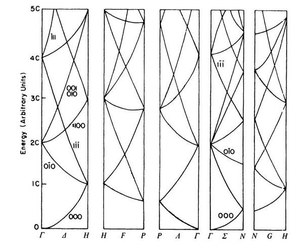
In Fig. 5.17 three important directions in k-space are inserted into the first Brillouin zone of a bcc lattice. They are the [100] direction from the origin (r) to point H, the [110] direction from T to N, and the [111] direction from T to P.14 These directions are commonly labeled by the symbols A, S, and A, respectively. Figure 5.18 depicts the bands, calculated by using (5.35), for these distinct directions in k-space. The sequence of the individual subgraphs is established by convention and can be followed using Fig. 5.17.
We now show how some of these bands are calculated for a simple case. We select the T — H direction as an example. We vary the modulus of the vector kTH = kx between 0 and 2p/a, the latter being the boundary of the Brillouin zone (see Fig. 5.16).15 For this direction, (5.35) becomes
where x may take values between 0 and 1. To start with, let G be 0. Then (5.36) reads
Figure 5.18. Energy bands of the free electrons for the bcc structure. The numbers given on the branches are the respective hi values (see the calculation in the text). Compare to Fig. 5.6.
(see footnote 10), where
This yields the well-known parabolic E(k)-dependence. The curve which represents (5.37) is labeled (000) in Fig. 5.18, because h1, h2, and h3 in (5.13) are all zero for G = 0.
Now we let h1 = 0, h2 = —1, and h3 = 0. Then we obtain, by using (5.13) and (5.32),
Combining (5.36) with (5.38) and (5.39) provides
(see footnote 10), which yields for
and for
We obtain the band labeled (0l0) in Fig. 5.18. Similarly, all bands in Fig. 5.18 can be calculated by variation of the h values and k-directions and by using (5.35).
The free electron bands are very useful for the following reason: by comparing them with the band structures of actual materials, an assessment is possible if and to what degree the electrons in that material can be considered to be free.
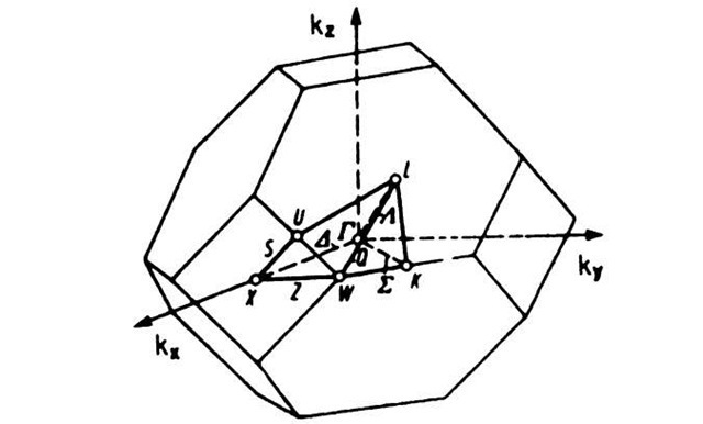
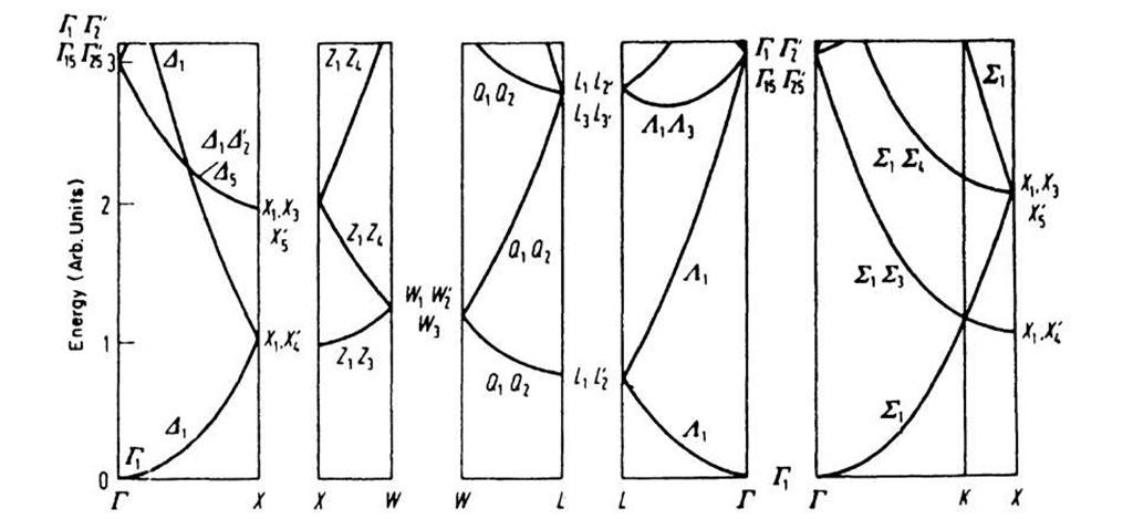
In Figs. 5.19 and 5.20 the first Brillouin zone and the free electron bands of the fcc structure are shown.
Figure 5.19. First Brillouin zone of the fcc structure.
Figure 5.20. Free electron bands of the fcc structure. The letters on the bottom of the graphs correspond to letters in Fig. 5.19 and indicate specific symmetry points in k-space.


![tmp6C206_thumb[2] tmp6C206_thumb[2]](http://what-when-how.com/wp-content/uploads/2011/07/tmp6C206_thumb2_thumb.jpg)

![tmp6C209_thumb[2] tmp6C209_thumb[2]](http://what-when-how.com/wp-content/uploads/2011/07/tmp6C209_thumb2_thumb.jpg)
![tmp6C210_thumb[2] tmp6C210_thumb[2]](http://what-when-how.com/wp-content/uploads/2011/07/tmp6C210_thumb2_thumb.jpg)

![tmp6C214_thumb[2] tmp6C214_thumb[2]](http://what-when-how.com/wp-content/uploads/2011/07/tmp6C214_thumb2_thumb.jpg)
![tmp6C215_thumb[2] tmp6C215_thumb[2]](http://what-when-how.com/wp-content/uploads/2011/07/tmp6C215_thumb2_thumb.jpg)
![tmp6C216_thumb[2] tmp6C216_thumb[2]](http://what-when-how.com/wp-content/uploads/2011/07/tmp6C216_thumb2_thumb.jpg)
![tmp6C217_thumb[2] tmp6C217_thumb[2]](http://what-when-how.com/wp-content/uploads/2011/07/tmp6C217_thumb2_thumb.jpg)
![tmp6C218_thumb[2] tmp6C218_thumb[2]](http://what-when-how.com/wp-content/uploads/2011/07/tmp6C218_thumb2_thumb.jpg)
![tmp6C219_thumb[2] tmp6C219_thumb[2]](http://what-when-how.com/wp-content/uploads/2011/07/tmp6C219_thumb2_thumb.jpg)
![tmp6C220_thumb[2] tmp6C220_thumb[2]](http://what-when-how.com/wp-content/uploads/2011/07/tmp6C220_thumb2_thumb.jpg)
![tmp6C221_thumb[2] tmp6C221_thumb[2]](http://what-when-how.com/wp-content/uploads/2011/07/tmp6C221_thumb2_thumb.jpg)
![tmp6C222_thumb[2] tmp6C222_thumb[2]](http://what-when-how.com/wp-content/uploads/2011/07/tmp6C222_thumb2_thumb.jpg)
![tmp6C223_thumb[2] tmp6C223_thumb[2]](http://what-when-how.com/wp-content/uploads/2011/07/tmp6C223_thumb2_thumb.jpg)
![tmp6C224_thumb[2] tmp6C224_thumb[2]](http://what-when-how.com/wp-content/uploads/2011/07/tmp6C224_thumb2_thumb.jpg)
![tmp6C225_thumb[2] tmp6C225_thumb[2]](http://what-when-how.com/wp-content/uploads/2011/07/tmp6C225_thumb2_thumb.jpg)
![tmp6C228_thumb[2] tmp6C228_thumb[2]](http://what-when-how.com/wp-content/uploads/2011/07/tmp6C228_thumb2_thumb.jpg)
![tmp6C229_thumb[2] tmp6C229_thumb[2]](http://what-when-how.com/wp-content/uploads/2011/07/tmp6C229_thumb2_thumb.jpg)
![tmp6C230_thumb[2] tmp6C230_thumb[2]](http://what-when-how.com/wp-content/uploads/2011/07/tmp6C230_thumb2_thumb.jpg)
![tmp6C231_thumb[2] tmp6C231_thumb[2]](http://what-when-how.com/wp-content/uploads/2011/07/tmp6C231_thumb2_thumb.jpg)
![tmp6C234_thumb[2] tmp6C234_thumb[2]](http://what-when-how.com/wp-content/uploads/2011/07/tmp6C234_thumb2_thumb.jpg)
![tmp6C235_thumb[2] tmp6C235_thumb[2]](http://what-when-how.com/wp-content/uploads/2011/07/tmp6C235_thumb2_thumb.jpg)
![tmp6C236_thumb[2] tmp6C236_thumb[2]](http://what-when-how.com/wp-content/uploads/2011/07/tmp6C236_thumb2_thumb.jpg)
