6.3
The three-phase symmetrical induction motor has three identical sinusoidally distributed windings displaced electrically 120° apart per set of poles. To simplify our approach as much as possible, consider a two-pole machine as depicted in Fig. 6.24 and compare this to Fig. 6.12 in the two-phase development. (Note that here we do not consider balanced windings on the stator, which were deliberately introduced for single-phase operation.)
Because of the addition of two additional axes plus the 120° phase displacement, the analysis becomes more complex due to the geometrical relationships; however, the approach parallels that for the two-phase development. Because of the additional winding, when we perform a transformation, as we did for the two-phase machine, it will require one more dimension in our transformation. However, because we are considering only balanced three-phase operation, it will not enter or complicate our analysis.
Let us now write the three-phase machine equations equivalent to Eqs. (6.17) to (6.24) for the two-phase machine.
![]()
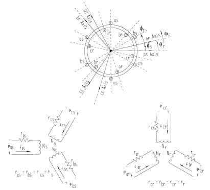
FIGURE 6.24 Balanced three-phase voltages and currents. Ns = stator turns per phase; Nr = rotor turns per phase.
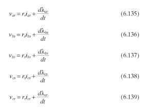
In the following equations, the L terms include both the leakage and magnetizing inductances, and the M terms are mutual inductance terms.
![]()

Unlike in the two-phase motor, where the stator windings and the rotor winding terms are orthogonal and hence zero, in the three-phase motor these terms are not orthogonal and therefore exist. However, because of the fixed relations between stator windings and also between rotor windings, these mutual inductances are constants. The mutual inductances between stator and rotor windings are functions of 6r.
Since both stator windings are fixed at 120° electrical apart, and assuming the material coupling varies as the cosine of the angle between them, the mutual inductances are as follows:

Here Ms is the maximum value of the mutual coupling—namely, where their axes are the same. Now the rotor windings again have the same relationship to each other as the stator windings; hence, the mutual inductors between rotor windings can be written as follows:

Also, because of the symmetrical balanced windings, the self-inductances and the leakage inductances are as follows:

We now turn our attention to the mutual coupling between stator and rotor windings. By referring to Fig. 6.24 and being aware of axis orientation, we have the following:
![]()
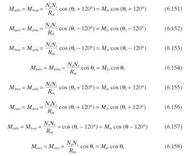
In the development of the two-phase and single-phase motors we made a transformation to remove the time-varying mutual inductances, then refined the rotor quantities in terms of stator terms. This time we choose to reverse the order, which makes no difference; however, this author believes it to be simpler. Here we refer the rotor quantities in stator terms as we did for the two-phase motor.
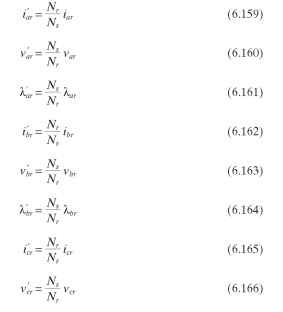
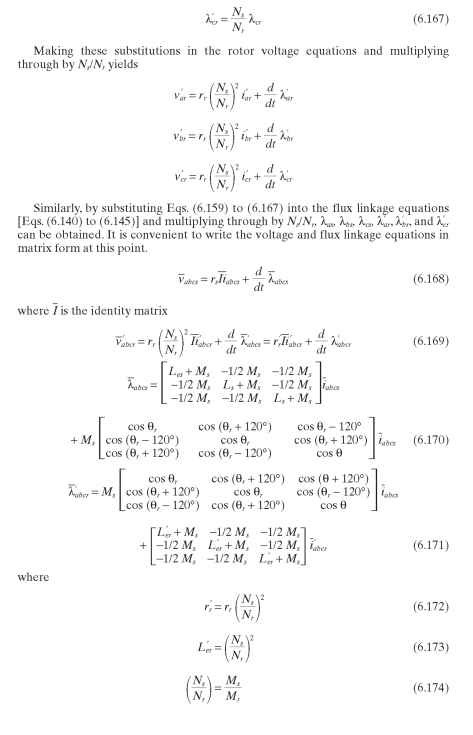
Note that these six equations are dependent on 6r; hence, a change in variable is appropriate, as was done in the two-phase approach. However, since we have three stator and three rotor variables, the transformation must be of third order. This was mentioned earlier. Thie transformation removes the dependency on 6r
One suitable power-invariant set of transforms for the stator and rotor variables, respectively, follows.
Stator:
Rotor:
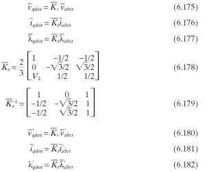

If these transformations [Eqs. (6.179), (6.183) and (6.184)] are introduced into Eq. (6.171), and the zero sequence is designated since we are considering a balanced three-phase machine, we have the following for all six voltage equations.


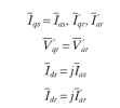
Since in the equivalent circuit we are interested in only one phase fo_r balanced operation, all we need in the preceding matrix are the voltage equations Vqs and Vqr.Writ-ing these equations and making the substitutions, we have the following (capitals indicate steady-state quantities):
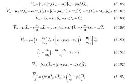
If we are not considering a double-fed motor that is a squirrel-cage induction motor,
V’ar = 0.
Using Eqs. (6.186) through (6.193), we can draw the equivalent steady-state circuit shown in Fig. 6.25 for one phase of the three-phase squirrel-cage motor, not considering core losses.
It is interesting to note that the magnetizing reactance here is 3/2 as large as the magnetizing reactance for the two-phase or single-phase motor.
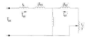
FIGURE 6.25 Simplified equivalent circuit of one phase of a polyphase motor.
