6.2.7
For applications where unbalanced conditions occur, C. L. Fortesque devised a process whereby unbalanced systems can be reformed into a system of balanced networks. The number of balanced networks required is the same as the number of degrees of freedom which occur in the unbalanced system. For example, an unbalanced three-phase power system, which has three degrees of freedom, requires three balanced networks.
In the case of an unbalanced two-winding single-phase motor having a main and auxiliary winding, two networks are required. Fortesque named these two balanced
networks the positive and negative sequence networks simply because they rotate in opposite directions. In terms of the motor in question, this is the same as the double-revolving-field theory, where we have two fields for each winding, one going CCW and the other CW. The CCW rotation is usually referred to as the positive sequence, whereas the CW rotation is referred to as the negative sequence.
The technique is powerful in that through the transformation we end up with balanced networks which we are able to handle. In the case of the two-degree network, the two components of each of the CCW (forward) and the CW (backward) are orthogonal to each other.
If we define the CCW rotation of the fields of both the main and auxiliary windings as progressing from the auxiliary to the main winding, we can then draw these components—for example, in terms of the currents in these windings, Im and Ia. On the other hand, the CW rotation is a transition from the main winding to the auxiliary winding. Consider the motor with unbalanced stator windings shown in Fig. 6.20.
![]()
The sequence relationships are represented in Fig. 6.21. Now, Fortesque defined the currents as follows:
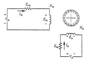
FIGURE 6.20 Motor circuit with unbalanced windings.
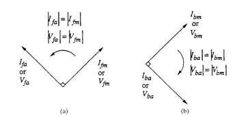
FIGURE 6.21 Sequence relationship of motor with unbalanced windings: (a) forward (+), and (b) backward (-).

At this point, the normal procedure is to pick either the main or auxiliary winding as the reference winding— i.e., to convert either the sequence components of the main in terms of the auxiliary or vice versa. The normal procedure is to use the latter approach, which can be seen in Fig. 6.21.
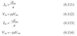
We have now resolved the auxiliary winding currents and voltages in terms of the orthogonal of forward and backward components. That is:
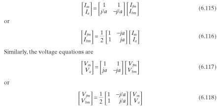
The second matrix allows us to find the forward (+) and the backward (-) sequence components and voltages. The reference forward and backward loop circuit model then becomes as shown in Fig. 6.22.
Figure 6.22a, the forward sequence, is one of two forward motor models referred to the main winding. Figure 6.22b, the backward sequence, is one of two backward motor models referred to the main winding. This is because both auxiliary and main windings have a forward and backward field, for a total of four models. Note that Zf and Zb as defined here are twice the values defined in Fig. 6.17.
![]()
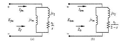
FIGURE 6.22 Field loop circuits: (a) forward, and (b) backward.
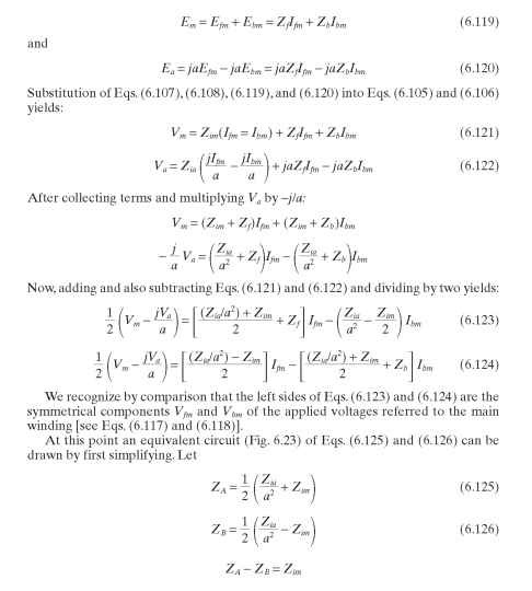
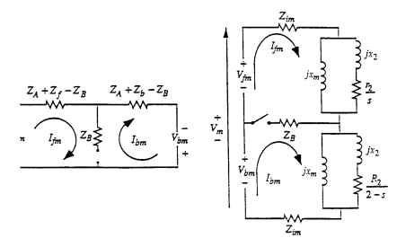
FIGURE 6.23 Combined equivalent circuit including forward and backward field components.

