6.4.3
Shaded-pole motors generally consist of a squirrel-cage rotor inside a stator which contains a shading band. The shading band acts as an auxiliary winding in this type of induction motor. In the 1890s it was discovered that a squirrel-cage motor with a salient-pole single-phase field will run if a portion of the pole is short-circuited with a winding or coil (Trickey, 1936). The theory behind the shaded-pole motor is that the shading coil causes the flux in that portion of the pole to lag a small fraction of
the time cycle behind the flux in the main part of the pole, causing the points of maximum flux to progress around the motor, resulting in a rather poor rotating field which draws the rotor around with it, as in any induction motor. If there were no shading coil on the salient pole, the flux in that pole and in the air gap under it would simply alternate from north to south, and no rotation would be produced. The rotating field draws the rotor from the main pole toward the shading pole. There are two typical configurations of shaded pole motors, round-frame and C-frame. See Fig. 6.46 for a round-frame shaded-pole motor and Fig. 6.47 for a C-frame or skeleton-frame shaded-pole motor.
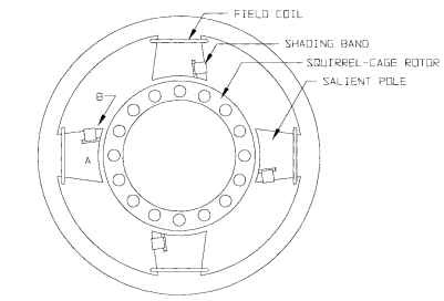
FIGURE 6.46 Round-frame shaded-pole motor.
Construction. The shaded-pole stator has a magnet wire winding and a shading band. The shading band is made of a horseshoe-shaped copper strip that is inserted after the stator lamination stack is formed. The ends of the strip can then be welded together. A drawing of a round-frame stator lamination is shown in Fig. 6.48. According to Chang (Chang and Karr, 1949; 1950), the pitch of the shading coil pitch 6s should be a minimum of 46.5° electrical, with a proper range between 46.5 and 60°. Trickey suggests using between one-quarter and one-half of the pole pitch for the shaded pole, or 45 to 90° electrical.
The rotor is usually a squirrel-cage type, consisting of steel laminations with copper or aluminum bars. After the rotor lamination stack is formed, the conducting material is cast into the slots and molded at the ends to form end rings, thus connecting all of the bars at each end. Copper conductors have lower resistance, but aluminum is easier to cast and is therefore more commonly used today.
Slot Combinations. Choosing a good combination of stator poles and rotor slots can be a challenge. Too few conductors can result in high zigzag leakage reactance, which reduces the motor output. According to Chang, the optimum number of rotor slots is about 11 to 13 per pole pair.
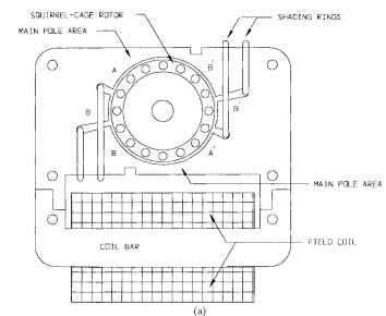
FIGURE 6.47 C-frame shaded-pole motor.
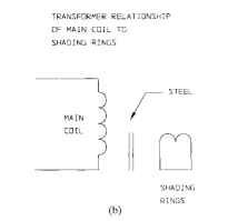
FIGURE 6.47 (Continued) C-frame shaded-pole motor.
Performance Calculations. Shaded-pole motors typically have low starting torque, low power factor, and low efficiency. A typical speed-torque curve is shown in Fig. 6.49.
The maximum rotor speed (or synchronous speed) is given by the following equation:

Figure 6.50 shows an equivalent circuit of a shaded-pole motor, as constructed by P. H. Trickey. Trickey uses the cross-field theory of induction
motors for his equivalent circuit, as opposed to the revolving-field theory. All of the equations in this subsection are derived from the cross-field theory. From this equivalent circuit, using Kirchhoff’s voltage laws, the following four equations can be derived:

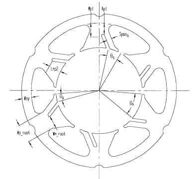
FIGURE 6.48 Shaded-pole laminations.

To solve these equations in terms of the various currents, the reactances and resistances of the motor must first be calculated. This step is much more complicated than it may sound. We begin by calculating steel areas and volumes. Unless otherwise mentioned, all length dimensions are in inches.

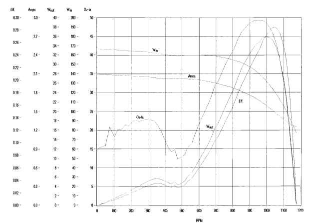
FIGURE 6.49 Typical shaded-pole motor performance curve.
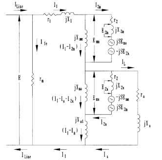
FIGURE 6.50 Shaded-pole motor equivalent circuit.
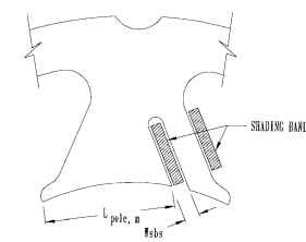
FIGURE 6.51 Main pole length.
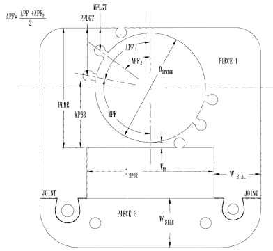
FIGURE 6.52 C-frame dimensions.
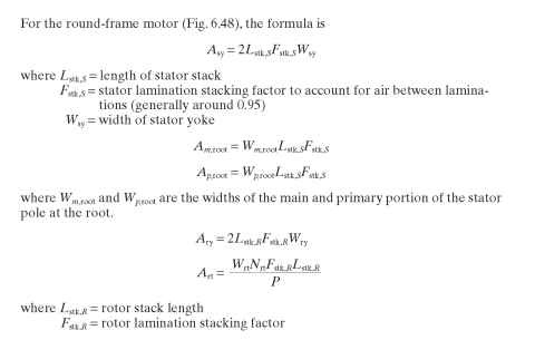
Nrt = number of rotor teeth P = number of stator poles
For round-frame motors, we also include the trapezoidal tooth portion of the pole, as in the following two equations:

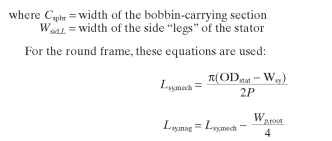
To calculate their respective magnetic volumes, the flux path lengths must now be calculated. Once again, there is a difference in the stator yoke calculations for the two stator shapes. For the C-frame motor, the following equations are used:

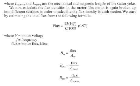
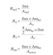
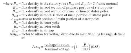
Now the BH curve(s) for the steel laminations are needed. A value of H (field intensity) must be recorded for each B value. The mmf drops can then be calculated by multiplying the field intensity (in amp-turns per inch) by the path length of the section. In other words:
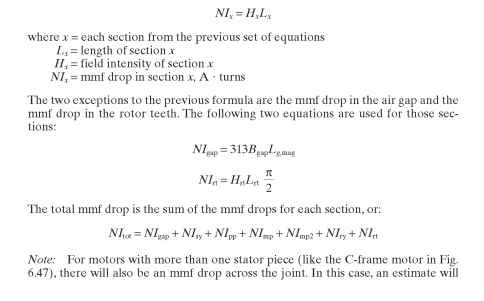
have to be made for the length and area, and then the mmf drop is calculated as with any other section.
The main saturation factor SFM is found by dividing the total mmf drop over the mmf drop in the air gap, or:
![]()
This brings us to the reactance equations. Before we begin, we must define a couple of multiplication factors. These are as follows:

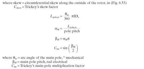
Similarly, for the auxiliary pole:
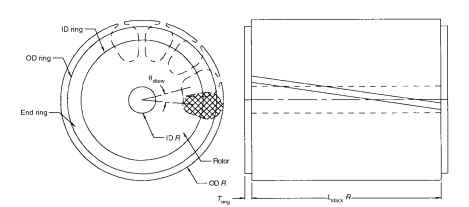
FIGURE 6.53 Rotor skew.
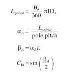
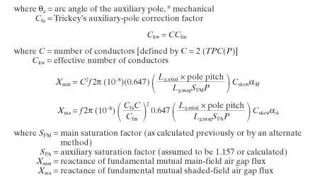
For the reader who would like a more in-depth analysis, Chang uses harmonics much more intensively than Trickey does. He calculates reactances at each harmonic and then takes the total of all of the harmonics, with some adding and some subtracting. For example, Chang calculates the mutual reactance of the nth harmonic using the following formulas:
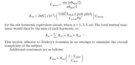
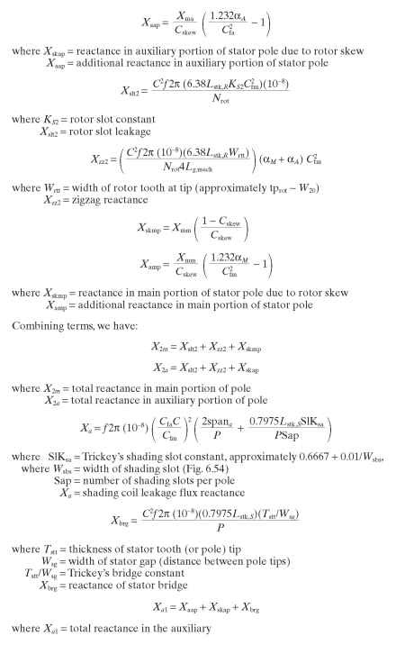
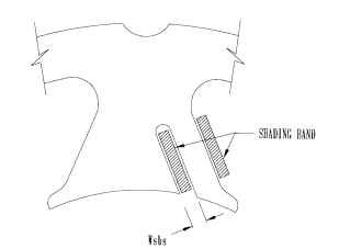
FIGURE 6.54 Shaded section of round-frame motor.
There is a difference here in equations for the C-frame motor and for the round-frame motor. The following equations are only for the round-frame motor.
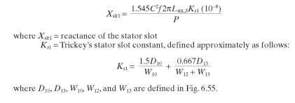
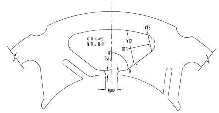
FIGURE 6.55 Dimensions for stator reactance.
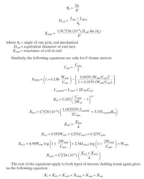
where X1 = reactance due to skew, harmonics, and leakage in the main
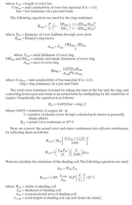
We now calculate the rotor resistance at the base temperature of 20°C, i^cld. Rotor resistance is made up of the bars and the ring. We calculate each of these and then take the sum. We begin with the bars, where the total area of the rotor bars is found by multiplying the area of one bar by the number of bars, or:

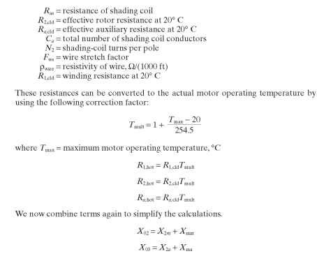
The previously calculated values allow us to solve the current equivalencies much more quickly. As an alternative to complex linear algebra, Trickey has solved the equations and broken them down into a series of B constants.The B constants allow a relatively quick calculation of the various currents. The following equation defines the total current going through the windings:
![]()
where V = source voltage
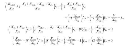
Referring to the equivalent circuit diagram and to the original four current equations, we now divide through by X02. Rearranging and multiplying the last three equations by j yields a set of equations that can be put into matrix form.
![]()
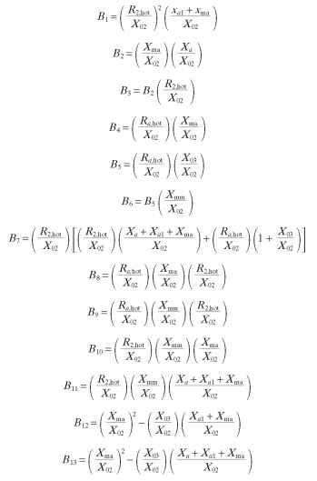
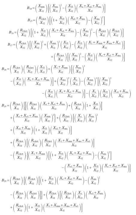
After solving these equations in terms of known values, in order to simplify calcula-tions,Trickey created a set of equations using the B constants. The equations for the 20 B constants are shown at the end of this subsection.
We then define eight more variables to simplify the final equations.
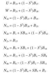
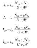
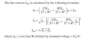
where S = ratio of speed to synchronous speed (S = 1 – slip SL) We can now rewrite the current equations as follows:
Slip-Dependent Calculations
Obviously, solving the equivalent circuit is only part of the problem in calculating the performance of a motor. Speed, torque, and power are also very useful to know. The following equations all take place at a given slip SL. The easiest variable to calculate is, of course, speed:
![]()
Experience has shown that torque is best calculated using two different equations. For speeds above breakdown, we first calculate power and then derive torque from the output power, as in the following set of equations:
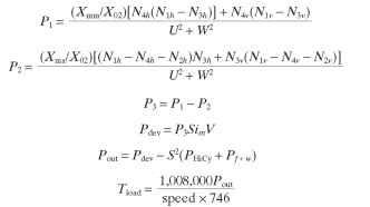

Unfortunately, these equations tend to predict torque values too high after breakdown. Therefore, after breakdown we use the following equation for torque:
![]()
To calculate efficiency, we must first know input torque. Input torque is equal to developed torque plus losses.We must include the I2R losses in each section, as in the following set of equations:
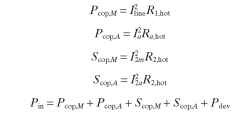
where Pin = input power, W
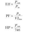
From here, calculating efficiency, power factor, and horsepower is simple:
Equations for Trickey’s B Constants
