6.4.4
Variables may be identified from the following list or from the figures.
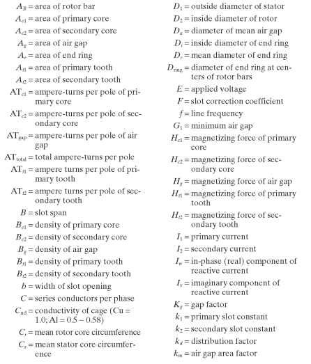
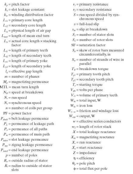
See Fig. 6.27 for a graphic representation of some variables.
Variables to Calculate:

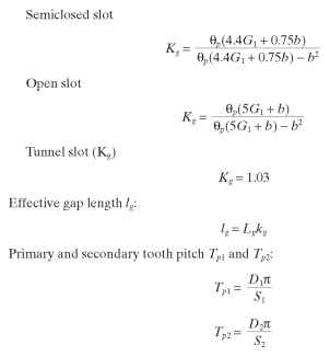
Calculations of Winding and Slot Constants
![]()
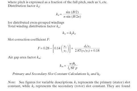
using the same set of equations, being careful to use the equation which most closely resembles that of the slot in question.
Round-Bottom Slot Constant k1 or k2 (note that Fis different for the two constants): Slot shape A (see Fig. 6.29)
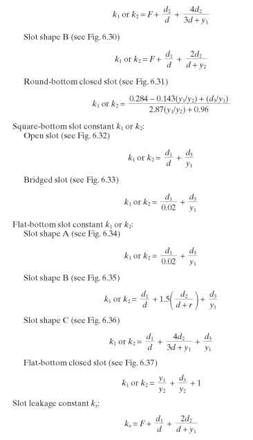
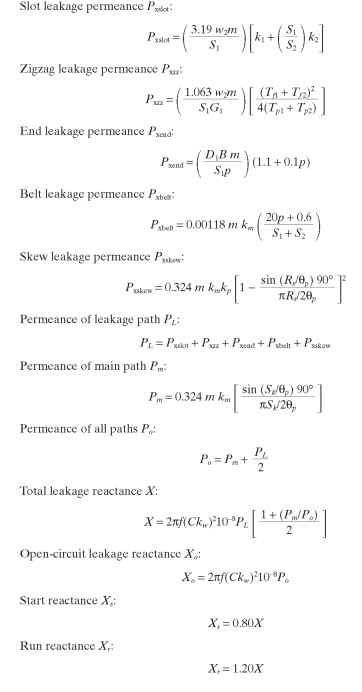
Leakage Reactances
Calculation of Magnetizing Current and Reactance
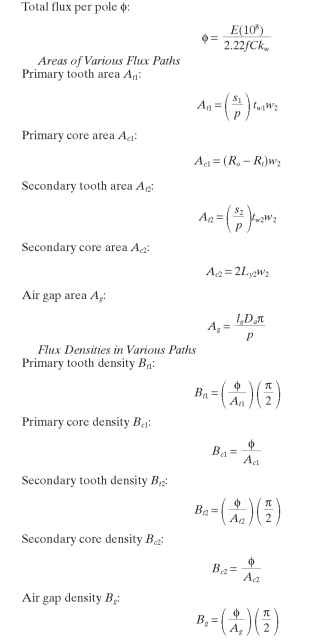
Magnetizing Forces. The magnetizing force of each path other than the air gap is found by referring the preceding densities to the proper saturation curve and reading across to find the respective magnetizing force.
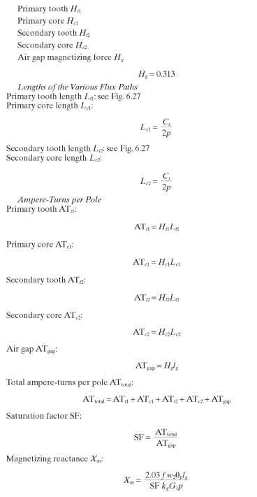
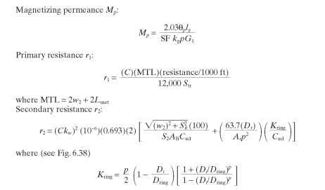
Calculation of Iron Losses Wfe

Friction and Windage Losses. Friction and windage losses are obtained by testing similar machines or by calculations from the bearing manufacturers.
Performance Calculations
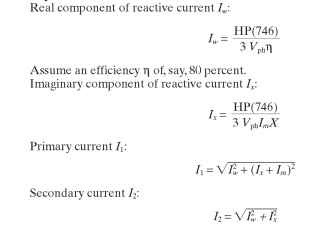
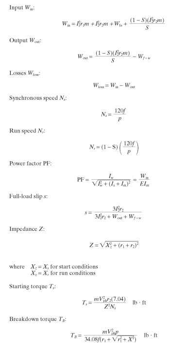
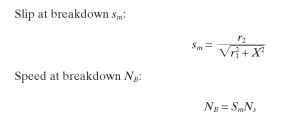
![]()
![]()
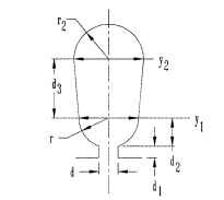
FIGURE 6.29 Round-bottom slot, shape A.
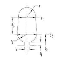
FIGURE 6.30 Round-bottom slot, shape B.
Primary and Secondary Slot Constant Calculations k and k2
Note: See figures for variable descriptions. k1 represents the primary (stator) slot constant, while k2 represents the secondary (rotor) slot constant. They are found using the same set of equations, being careful to use the equation which most closely resembles that of the slot in question.
Round-bottom slot constant k1 or k2 (note that F is different for the two constants):
Slot shape A (see Fig. 6.29)
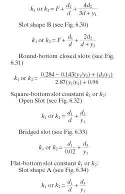
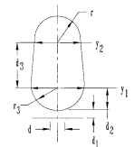
FIGURE 6.31 Round-bottom closed slot.
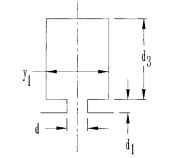
FIGURE 6.32 Square-bottom open slot.
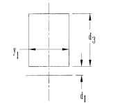
FIGURE 6.33 Square-bottom bridged slot.
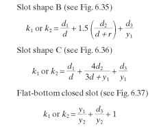
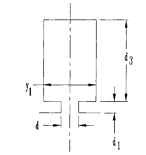
FIGURE 6.34 Flat-bottom slot, shape A.
Leakage Reactance Calculations
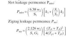
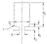
FIGURE 6.35 Flat-bottom slot, shape B.
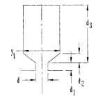
FIGURE 6.36 Flat-bottom slot, shape C.
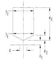
FIGURE 6.37 Flat-bottom closed slot.
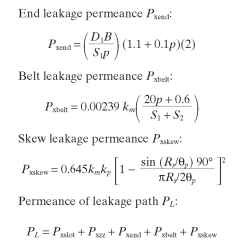
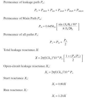
Motor Constant Calculations for Single-Phase Motors

Calculation of Magnetizing Current and Reactance
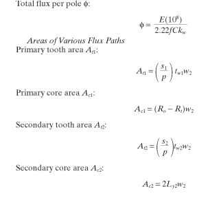
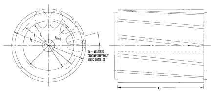
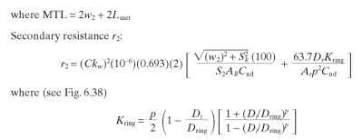
FIGURE 6.38 Resistance ring dimensions.
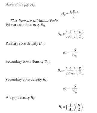
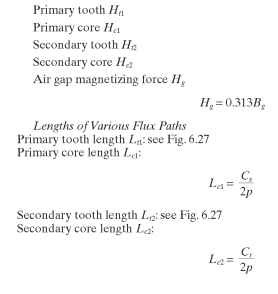
Magnetizing Forces. The magnetizing force of each path other than the air gap is found by referring the preceding densities to the proper saturation curve and reading across to find the respective magnetizing force.
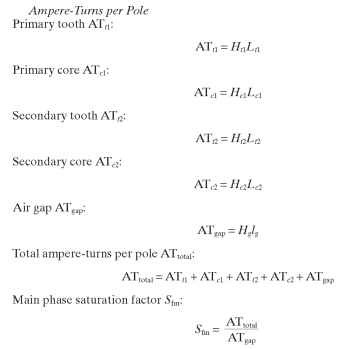
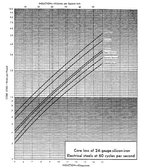
Calculation of Iron Losses (Fe Loss)


Friction and Windage Losses. Friction and windage losses Wf + w are obtained by testing similar machines or by calculating bearing friction and windage from the bearing supplier’s information.
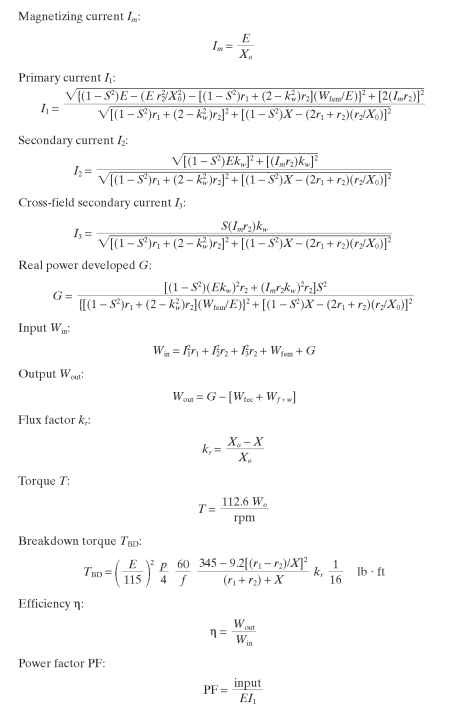
Performance Calculations for Single-Phase Induction Motors Full-load slip s:
![]()
FIGURE 6.39 Core loss curve.
![]()
Starting Torque Calculations for Split-Phase Motors. See the split-phase schematic in Fig. 6.40. Effective resistance of main R:
![]()
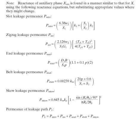

FIGURE 6.40 Single-phase split phase diagram.
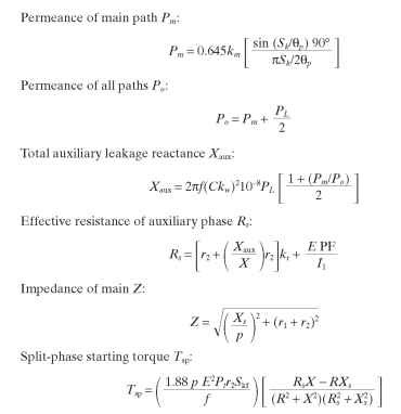
Starting Torque Calculations for Capacitor-Start Motors. See the capacitor-start

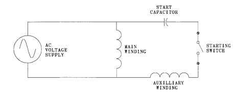
FIGURE 6.41 Single-phase capacitor-start diagram.

