30.3.
Window Winding and Central Door Locking
Although central door locking and electric windows are considered in the past as luxury items but nowadays are becoming quite common and the operation is much similar.
30.3.1.
Electrically-operated Windows
In an electric window system, a D.C. permanent magnet motor is normally used to operate each window, and a three-position rocker switch changes the polarity for providing up-and-down motion of the window. Four main window switches, one for each window are installed on the driver’s panel, and an isolation switch is also added to disconnect the supply to the rear windows. Two relays control the current to each motion and are powered by a common feed.
A gearbox forms the drive between the motor and the window glass and amplifies the torque sufficiently to undertake upward motion of the window, which is more difficult than the downward motion. The gearbox drives either a flexible rack or acts directly on to the window winding mechanism similar to a manual system.
To limit the current during overloading one or more thermal cut out switches are installed in the circuit, sometimes in the motor. The cut-out is opened if the operating switch is held closed when the window has reached its limit of movement or in case where free movement of the glass is arrested by ice. A main overload switch, if used, is generally of a type requiring resetting after encountering an overload situation.
The circuit in Fig. 30.22 is for electric operation of a rear passenger window, but the balance of the circuit has not been shown for simplicity. The motor in this layout is powered directly through the ignition switch. An additional rear-window switch can be incorporated to adjust the window, but this can only be operated when the driver’s isolation switch is closed. The ganged switch supplies the current with suitable polarity to rotate the motor in the required direction during the operation of the window.
30.3.2.
Central Door Locking
A door locking system normally locks all doors, including the tailgate or boot simultaneously when the driver’s door lock is activated. When the key is turned or the driver’s door lock button is operated, the electrical system actuates all the locking actuators installed adjacent to the door locks. Unlocking the door takes place in the similar way except the locking actuators work in the opposite direction. Both for convenience and safety reasons, a mechanical latches system is fitted, which unlocks each door manually from inside the car.

Fig. 30.22. Electric windows circuit.
Door-lock Relays.
The door locking system consumes a large current during the period of its operation. In order to minimize operation time, door-locking circuit normally utilizes the charge or discharge action of a capacitor. The current to the locking mechanism is cutoff after a set time interval, which represents the normal locked or unlocked conditions.
Various types of control are incorporated to provide the locking/unlocking pulse for operation of the actuators. In some designs two relays are used, one for locking and the other for unlocking the doors. A transistorized switching circuit controls these relays. The circuit is timed by the charge-discharge action of a capacitor to provide a current pulse length sufficient to actuate the locks (Fig. 30.23).
An alternative control system utilizes the discharge current from a previously charged capacitor to energize the relay. When the door key is turned to close the appropriate switch, the capacitor releases its charge through the relay coil. When the capacitor is fully discharged the relay opens and the system goes out of action (Fig. 30.24).
Doors lock Actuators.
The electrical methods for door lock mechanism use electromagnet solenoids, linear motors or permanent magnet rotary motors. In each case the reversing action takes place by changing the polarity. Figure 30.25 illustrates one layout for operating a door lock.
Now-a-days almost all door actuators use small motors which, via suitable gear reduction, operate a linear rod in either direction to lock or unlock the doors. A simple motor reverse circuit is utilized for the required action. Figure 30.26 illustrates a typical door lock actuator.

Fig. 30.23. Central door locking circuit (transistorized control).

Fig. 30.24. Central door locking circuit (capacitor control).
External Circuit.
The layout of the complete circuit is presented in Fig. 30.27, where the driver’s door switch operates the locks on four^doors.
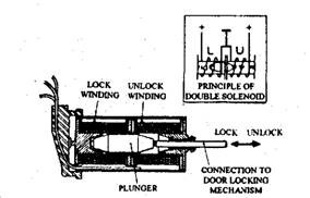
Fig. 30.25. Door locking actuator (electrical method).
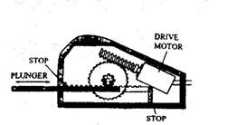
Fig. 30.26. Door locking actuator (using reduction gear).
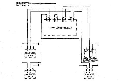
Fig. 30.27. External circuit for central door locking.
More sophisticated systems are now becoming popular for consideration of safety as well as improved comfort. The following features are now available from many manufacturers.
• One shot up or down.
• Inch up or down.
• Lazy lock.
• Back off.
The complete system uses an electronic control unit containing the window motor relays, switch packs and a link to the door lock and sun roof circuits as shown in the form of a block diagram in Fig. 30.28. When a window is operated in one shot or one touch mode the window is driven in the chosen direction until either the switch position is reversed, or the motor stalls or the ECU receives a signal from the door lock circuit. One shot operation has a problem that if a child is trapped in the window a serious injury may occur. To avoid this problem, a back off
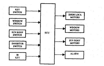
Fig. 30.28. Block diagram showing links between door locks, windows and sun roof
(controlled by an IR key).
feature is incorporated. An extra commutator is added to the motor armature, thereby a signal is produced through two brushes, which is proportional to the motor speed. When closing if the rate of change of speed of the motor is detected as being below a certain value then the ECU reverses the direction of operation of the motor until the window is fully open.
By counting the number of pulses received the ECU can know the window position. The ECU must be initialized to determine the window position. For initiatizing the motor is operated to drive the window first fully open, and then fully closed. This is necessary for the one shot close operation of the window. On some systems, Hall effect sensors are utilized to detect motor speed. Other systems sense the current drawn by the motor and this is used as an indication of speed.
The lazy lock feature, if incorporated, fully secures the car by one operation of a remote infra-red key. This is achieved through the link between the door lock ECU and the window and sun roof ECUs. Once a signal is provided, this causes all the windows to close in turn, then the sun roof closes and finally the doors lock. The alarm is also set if required. When the window close in turn an excessive current demand is avoided.
30.3.3.
Maintenance
To systematically diagnose the faults in a central door-locking arrangement, the circuit should be initially checked to pinpoint the fault to a particular section before the trim is removed to expose the locking mechanism. Many manufacturers provide a table which is used to compare the results with the fault finding chart normally included in the manufacturer’s service manual. It is necessary to refer to the circuit diagram or appropriate fault-diagnosis chart before applying either full battery voltage or an ohmmeter to a particular cable or test pin. This is particularly important when the unit uses delicate semiconductor or ICs designed to operate at a voltage well below that of the battery.
Following is the check-out sequence as applied to a system similar to that shown in Fig. 30.27. When all locks fail to operate, the fault may be caused due to (a) no power to the relay unit, (6) defective switch, and (c) faulty relay unit. All of these possible faults should be checked one by one to narrow down the actual cause. In this regard the following method can be used :
(i) After inspecting the circuit breaker, the input voltage to the relay unit pins 3 and 4 should be checked.
(ii) Once the supply is correct, a jumper lead should be used to connect pin 5 to earth to reproduce the switch action. This confirms if the switch section of the circuit is faulty.
(Hi) If the input voltage and switch are alright, the output voltage at one of the pins 1, 2, 7 or 8 should be measured keeping the switch operated. If battery voltage is not shown at the instant the switch is closed, then the relay is defective and requires replacement.
This procedure can be reduced considerably by utilizing a fault diagnosis charge (Table 30.1). Based on the result given by a particular test the path in the chart is followed.
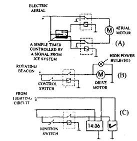
Fig. 30.29. Electric aerial, rotating beacon, cigar lighter and clock circuit.
30.3.4.
Auxiliary Systems.
Some vehicle electrical systems which are not covered elsewhere are shown in Fig. 30.29. A cigar lighter, clock, rotating beacon and electric aerial are the system shown in the figure.
