13.2.
Vehicle Circuits and Systems
Vehicle electrical systems use up to the mid-1970s were relatively simple, containing just a
few circuits for lighting, wiper and heater motors, and a points-type ignition system. The 1980s witnessed exceptional advances in electronics technology, which brought about a remarkable growth in the function of the electrical system so that a rapid increase in the number and complexity of electrical modules incorporated into vehicle resulted. As a consequence vehicle electrical wiring systems have become alarmingly complex, incorporating more and more connectors, terminals, relays and control units.

Fig. 13.39. Battery circuit.
For the automobile technician to understand the operation of the vehicle electrical system it is quite normal to divide the system into a number of smaller sub-systems, so that in case of an electrical fault diagnosis can then be confined to the particular affected sub-system.
13.2.1.
Vehicle Systems
The main parts, systems and circuits of the vehicle electrical systems are as follows :
Battery. This unit supplies the electrical energy for vehicle electrical systems, during non-operation of the engine. Also it provides energy for cranking the engine during starting. The battery acts as a storage unit for the electrical energy (Fig. 13.39).
Charging System. After the battery has discharged some of its energy, electrical energy must be supplied to restore its fully charged state. The charging system offers this service and also, provides energy to the complete electrical system at all times during operation of the engine.
Starting System. Instead of the manual cranking of the engine with a starting handle, the electrical starting system makes the engine to start at the touch of a switch.
Ignition System. For operation of the engine each cylinder needs a spark at the appropriate time. To produce a spark a voltage much higher than that given by the battery is necessary. The ignition system transforms the battery voltage to a value often in excess of 20 kV to produce the spark.
Lighting System. For security purposes the vehicle must have different lights to show its presence and also to help the driver to visualize the movement of the vehicle. Bright driving lights must not dazzle the drivers of oncoming vehicles and hence some arrangement is incorporated to dip the main beam.
Auxiliary Equipment. In addition to the main systems, many other auxiliary items are installed in vehicle. These components have been increased over recent years and will continue to expand to improve vehicle operation, driver control and comfort of passengers.
The equipment include windscreen wipers and washers, horns, direction indicators and hazard warning systems, heating and ventilation systems, door-locking actuators, electrically-operated windows, electrical seat adjustment, electrical mirrors, electric sun roof operation, electric dipped rear view mirror, rain sensor, air-bag, type pressure warning, cruise control systems, adaptive noise control, vehicle security systems and other instruments.
In-car Entertainment and Communication. This is often classed as an auxiliary, but due to the sophistication and expanse of modern equipment this section has been separated from the general auxiliaries. These include in car-entertainment like radios, tape players, TVs etc., mobile communications, and interference suppression.
Vehicle Circuits.
After identification of the main systems each system is generally arranged into its appropriate circuit. Each electrical circuit requires a source of energy. However one electrical feed wire may be incorporated into a number of circuits. If this feed wire fails, then indication of fault occurs in more than one system.
Electronic Systems.
Normally the word ‘electronic’ is applied to any part or system, which uses a semiconductor device. Nowadays these devices are commonly used in a number of the basic systems in the automobile. Additionally ‘electronics’ are contributing considerably for engine management, which constitutes controlling the ignition and fuel systems, automatic transmission control and many other specialist services relating to sensing or controlling the performance of a particular part.
13.2.2.
Vehicle Electrical Distribution System
The increased application of electrical and electronic systems in automobiles has necessitated the use for complex electrical distribution systems. A typical mid-priced, medium-size European car of the 1990s uses more than 1.5 km of wiring and more than 2000 terminals, connectors and relays, and the weight of such an electrical distribution system exceeds 30 kg. The wiring harness is the major component of the electrical distribution system. This contains bundles of cables, which connect all of the electrical parts, sensors and actuators with electronic control units in a vehicle. It serves two primary functions. These include (i) to act as a power distribution network, and (ii) to act as an information distribution network.
The majority of vehicle breakdowns are caused by electrical failure, so vehicle reliability is critically dependent upon good wiring harness design and implementation. Generally, the wiring harness is divided into a main harness that runs the length of the vehicle connecting the battery to the charging system, vehicle interior, lighting and accessory circuits, and various sub-harnesses, such as door wiring, tailgate wiring, and roof wiring. For facilitating vehicle assembly and servicing, connector blocks are used for connecting the sub-harnesses to the main harness.
Cables.
Electrical cables used in automobiles contain several stands of annealed copper wire bunched together and encased in an insulating covering (generally PVC-polyvinyl chloride) of 0.2-0.4 mm thickness. Each strand of copper wire is typically about 0.32 mm diameter. The number of strands determines the size and hence current-carrying capacity of the cable. Applications requiring greater flexibility, such as in a tax-door sub-harness, flexible cable made from 0.18 mm annealed copper strands, are used. For high temperature applications (usually in the engine compartment) ordinary PVC insulation is not suitable, and hence special plastics such a PTFE, PFA, FED or X-ray treated cross-linked PVC or polyethylene are used.
Generally, cables are specified as per the strand diameter and number of strands. A cable with specification as 7/0.3 is made from seven strands each of 0.3 mm diameter. If an insulation thickness of 0.35 mm is provided, a cable normally has a finished diameter of about 1.6 mm and is suitable for carrying current up to about 4 A.
To reduce costs, manufacturers use the thinnest possible cable for a particular application in a vehicle, without causing too much voltage drop. As a rule of thumb, a maximum voltage drop of 5% (i.e. 0.6 V in a 12 V system) is allowed for general lighting and control circuits. Normally, a current rating of about 8.5 A per square millimetre of cable cross-section is assumed. A reduced rating of about 6 A per square millimetre is considered for continuously loaded cables. Table 13.1 summarizes typical sizes, current ratings and resistances for commonly used wires in automobiles.
Table 13.1. Sizes and Current Ratings of Wires used in |
|||
| Automobile Wiring Harnesses. | |||
| Wire Size | Current Rating (A) | Resistance per metre | Application |
| 7/0.3 | 4.0 | 0.032 | Side/tail lamps, |
| 9/0.3 | 5.5 | 0.027 | signals, music |
| 14/0.3 | 9.0 | 0.017 | system |
| 28/0.3 | 17.5 | 0.009 | Light, heater, motors |
| 44/0.3 | 25.0 | 0.006 | |
| 65/0.3 | 35.0 | 0.004 | Alternator, main |
| 84/0.3 | 42.0 | 0.003 | supply to fuse |
| 97/0.3 | 50.0 | 0.002 | box |
| 120/0.3 | 60.0 | 0.002 | |
| 37/0.9 | 170.0 | 0.001 or less | Starter motor |
Harness Routing.
Generally the bundle of cables with a diameter in the range 10-30 mm is used for the wiring harness. This bundle is carefully routed around the vehicle, avoiding the locations having trim screws, mounting bolts and extremes of temperature (exhaust system, air-conditioner components). At regular intervals, clamps are used to secure the harness properly to the body-shell so that it is against stressing of the wires. Rubber grommet is fitted at the places where the harness passes through a metal panel thereby protecting the harness against chafing and preventing the ingress of moisture and dirt.
The places where many cables run (for example, the rear light clusters), ribbon cable is preferred to use. Ribbon cable is simply a number of conductors laid side-by-side to make a wide, flat, harness and it is easy to conceal this type of cable underneath carpeting and along flat body panels.
Cable Colour Coding.
Some form of cable colour coding is provided with the automobile wiring harnesses for fault diagnosis and repair works. The colour codes used invariably vary from one manufacturer to another and sometimes between different models from the same manufacturer. Therefore, it is important to refer to the vehicle repair manual before taking up any electrical work.
Most coding systems use a base cable for each cable and then add a contrasting tracer. These colours then are indicated by a letter code on the vehicle wiring diagram, which is usually in black and white. For example, a cable marked ‘BO’ on a wiring diagram indicates black with an orange tracer. To bring down costs, the ‘tracer’ can be a thin painted line added only where the cable enters a connector. Some manufacturers use just a few base colours and then code the wires by adding small coloured sleeves at each end. Table 13.2 provides some of the main colours used for the principal circuits.
Table 13.2. Colours for Circuits. |
|||
| Circuit | BSI | Letter Code British | Letter Code German |
| Earth connections | black | B | SW |
| Ignition circuits | white | W | WS |
| Main battery feed | brown | N | BR |
| Side lamps | red | R | RT |
| Auxiliaries controlled by ignition switch | green | G | GN |
| Auxiliaries not controlled by ignition switch | purple | P | VI |
| Headlamps | blue | U | BL |
In view of the different standards used by manufacturers, it is wise to consult the wiring diagram for the vehicle whenever a particular cable or circuit has to be identified.
Circuit Numbering.
In addition to colour coding some manufacturers also use numbers to indicate the circuits. Table 13.3 provides the main numbers used as recommended by the German DIN standard.
| Table 13.3. Terminal Marking According to DIN Standard. | |
| Circuit Number | Application |
| 1 | Ignition, earth side of coil |
| 4 | Ignition, HT output |
| 15 | Ignition, feed (un-fused) |
| 30 | Feed from battery |
| 31 | Earth |
| 51 | Alternator output |
| 54 | Ignition, feed (fused) |
| 56 | Headlamps |
| 58 | Side/tail lamps |
| 75 | Accessories |
Sub-circuits are identified by adding a number or letter after the main number; e.g. 15-4 is a sub-circuit based on circuit 15, the ignition feed circuit.
Printed Circuits.
A printed circuit board (PCB) is used, instead of a number of interconnected cables, to provide a more compact and reliable circuit arrangement. It is particularly suitable for instrument panel and component sub-assemblies incorporated in electronic control units (Fig. 13.40).
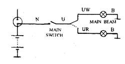
Fig. 13.40. Printed circuit diagram for a wiper control.
During the process of manufacturing, the circuit board initially has an insulation base on to which a thin layer of copper is bonded. After printing the circuit image on the copper layer, the board is then immersed in acid. This removes the unwanted copper layer and leaves a number of thin conductors on to which the component parts are soldered. In the case of PCB for an instrument panel (Fig. 13.41), the circuit board is connected to the various cables by means of a multi-pin lug.
Since the copper layer forming the printed circuit is very thin, it must be handled with care and should not face a heavy current. Accidental breakage of the copper foil can be repaired by careful soldering using the minimum amount of heat.

Fig. 13.41. Printed circuit board for instrument-panel.
Light-bulb holders A:
1. Speedometer light 2. Side, rear, and licence-plate lights
3. Headlight dipped-bear warning light 4. Headlight main-beam warning light
5. Rear-screen demister warning light 6. Front-fog-light’on’warning light
7. Brake-circuit incident and hand brake ‘on’ warning light
8. Oil-pressure warning light
9. Battery-charging warning light 10. Brake-pad-wear warning light
11. Hazard warning light
12. Rear-fog-light ‘on’ tell-tale
13. Choke’on’warning light
14. Low-fuel warning light
15. Automatic transmission incident warning light
16. Clock light
17. Direction-indicator light
18. Coolant-temperature light
19. Fuel-gauge light
Connector B:
1. Side, rear, and licence-plate warning light
2. + after ignition switch (not in use)
3. Headlight dipped-beam warning light
4. Headlight main-beam warning light
5. Rear-screen demister warning light
6. Front-fog-light’on’warning light
7. Brake-circuit incident and hand-brake’on’warning light
8. Oil-pressure warning light
Connector C:
1. Battery-charging warning light
2. Brake-pad-water warning light
3. + after ignition switch
4. Coolant-temperature-gauge light
5. Fuel-gauge light
6. Lighting
Connector D:
1. + after ignition switch
2. Low-fuel warning light
3. Choke ‘on’ warning light
4. Rear-fog-light ‘on’ tell-tale
5. Hazard warning light
6. Earth
7. Direction indicators
8. Clock
9. Tachometer make and break
Terminals and Connectors.
Terminals are used to attach cables to components and connector is used to join the cables together.
Terminals. The fork and eyelet type terminals are occasionally used, and the quick connect or Lucar type (Fig. 13.42) are more commonly used in automobile applications.
An appropriate crimping tool (Fig. 13.42) is used to fit a terminal. The terminal should have a sound joint with the copper core. It must also be secured properly to the insulation covering to resist breakage due to vibration and to protect it from moisture, which can cause corrosion and provide a high resistance.
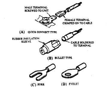
Fig, 13,43 Sign terminals.
Connectors.
Bullet connectors of the soldered and crimped forms are still used to join two or more cables. But more efficient types of connectors are used for greater security and improved protection against the ingress of salt and moisture, specifically when the connector has to handle low currents. Some E-type connectors, illustrated in Fig. 13.44, are environmentally protected types available in 3, 5, 7 and 9 way forms. The

Fig. 13.43. Crimping tool for fitting terminals.
sealing features of these connectors reduce the risk of electrical breakdown even when they are exposed to outside environment.
The design features of the Total Terminal Security (TTS) connector prevent terminal disengagement during assembly of the connector. This disengagement, called terminal back-out,
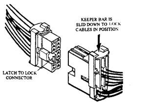
Fig. 13.44. Cable connector.
is arrested by the keeper bars in the plug and socket. Connector features also include a latch that locks the plug and socket together, and provision that permits only correct mating of the two parts.
Electronic control units (ESUs) for engine management systems, incorporate a connector that takes up to 12 cables with an inbuilt provision that enables the pins to mate progressively when the connector is fitted to the control unit. A connector suitable for this application is shown in Fig. 13.45. This type is protected against hostile environmental conditions and uses a latching system that retains the connector securely in position. Edge connectors (Fig. 13.46) are used to provide a low-resistance contact with a printed circuit board.
High quality connector sometimes requires the use of precious material like silver and gold for better conductivity but it becomes expensive so that rarely automotive manufacturers can afford this. The cheaper connectors can only be disconnected and rejoined about five times to produce a sound reliable connection and hence can cause problems during faults diagnosis. A connector built to an aeronautical specification can be separated many more times, but it is more than ten times costly.
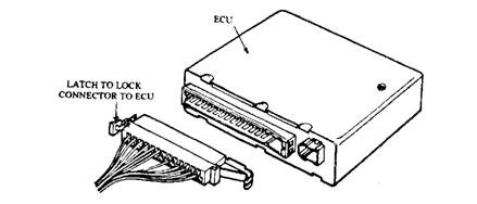
Fig. 13.45. Connection to an ECU.
Circuit Protection.
In the event of a short circuit, a higher current than normal flows from the battery so that the cable is overloaded and heated up. This can melt the cable insulation and may cause a fire. Also the battery discharges soon due to heavy current causing the vehicle to immobilize. A circuit-protection device, such as a fuse or thermal circuit breaker, reduces these problems to a great extent. When a fuse ‘blows’, it should be replaced with a fuse of similar rating. If this fuse also fails immediately, then the circuit
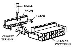
Fig. 13.46. Edge connector.
should be inspected to find the short circuit. Many faults are observed due to poor cable security or lack of protection at locations where the cable enters through holes in metal parts of the vehicle.
Fuses.
Fuses are available in different forms as shown in Fig. 13.47. The glass cartridge type is the oldest, which uses a sort length of tinned wire joined at each end to a metal cap and enclosed in a glass cylinder. A strip of paper, colour coded and marked with fuse rating, is placed close to the wire. Different ratings are manufactured to suit the various circuits. If the current exceeds the rating, the fuse ‘blows’, that is the wire melts, and the circuit is broken.
Same fuses, e.g. ceramic type, are rated according to the continuous current that can be carried by the fuse. This current is normally half the current required to melt the fuse. Fuses are either mounted centrally on a fuse board or placed in a separate fuse holder ‘in-lined’ to protect an auxiliary. Some vehicles install a fusible link in the main output lead from the battery. This heavy duty fuse melts if an accident causes the main cable short to earth.

Fig. 13.47. Types of fuses.
Thermal Circuit Breakers. A bimetallic strip is used in a circuit breaker to control a pair of contacts in the main circuit. An overload current heats and bends the strip, which opens the contacts and temporarily interrupts the circuit. When this is installed in a
lighting system, a short circuit causes the light to go off and on repeatedly so that the driver can bring the vehicle to rest safely. A single fuse of the normal type placed in the lighting system causes the light to go off totally in the event of its failure giving rise to a dangerous situation ; so separate fuses are used for each headlamp.
13.2.3.
Multiplex Wiring Systems
As the vehicle has incorporated more and more electrical system, the wiring harness servicing the electrical equipment has also increased, both in size and complexity. Since the early 1980s automotive engineers are trying for other methods to switch power to the various circuits around the vehicle, and multiplexing is one such technique.
Repeated use of a wire is the main feature of a multiplex wiring system. Each piece of information (from switches, sensors and ECUs) is converted into a digital (ON-OFF) signal and
transmitted serially throughout the system. The techniques is illustrated using a simple example in Fig. 13.48.
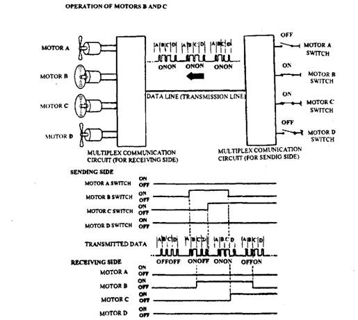
Fig. 13.48. Use of multiplexing to transmit signal information along a single wire.
The four motors A, B, C and D are operated from four switches. Information on the status of each switch is passed by the sending unit, in a predetermined sequence, along just one transmission line called a data line. The receiving unit decodes the digital data and operates relays or transistor switches, and provides current to the appropriate motor. Since each data is sent many times in every second, the response of the system appears almost instantaneous so far as the driver is concerned, giving a feeling as if the switches were wired directly to the motors. A multiplex system in practice incorporates many sending and receiving units, placed at strategic locations around the vehicle and all connected to the same data bus.
Advantages of Multiplexing,
Multiplex wiring systems have the following advantages over aconventional ‘peint’to^point’ wiring system.
U) Multiplex wiring harnesses are smaller and simpler, so that there is a saving on eest and weight.
(H) It is easy to have automated manufacture of the harness. (Hi) Harness installation on the vehicle assembly track can be much faster.
(iv) A reduction in the number of wires and connectors improves reliability.
(v) Self-diagnosis features can be incorporated into the AJB electronics, which helps the technician to trace faults.
Controller Area Network (CAN).
The Society of Automotive Engineers (SAE) Categorise multiplex wiring systems of the type described above as Class A systems. Class A systems are ‘low-speed buses’, but can transfer several thousand pieces of data per second. It is also suitable for use in the control of body electronic systems such as windows, sunroof, lights, etc. If data are required to be exchanged at a much faster rate (as is the case with engine and transmission management, ABS and traction control electrons), then Class B or Class C bus systems are necessary. During the 1980s many vehicle manufacturers proposed a number of such systems, notably ABUS (Volkswagen-Audi), VAN (consortium of French manufacturers) and J1850 (US manufacturers), out of which CAN (Bosch) became the most widely accepted standard for Europe.
Bosch in 1987 denned the Controller Area Network (CAN) as a class C system for intracar (within the vehicle) communications. Intel Corporation in 1988 produced the first network controller chip the 82526 CAN IC, so that CAN become a practical proposition for vehicle electronics. Consequently, CAN is expected to become the standard bus system for Europe and in 1990 it was proposed as an ISO standard (TC22/SC3/WG1). In 1991 Daimler Benz installed a CAN network in their new S-series Mercedes-Benz cars.
Basic Concepts of CAN.
CAN is a high speed serial data bus capable of transferring up to 1 million bits of data per second. The engine and chassis control ECUs can be connected to the common CAN bus. The direct mode of communication between the components makes it possible to reduce the number of sensors and actuators by ‘sharing” their information between the various ECUs. It permits to design vehicle electronic systems using ECUs from different suppliers with a minimum of interconnecting wiring. The CAN requires only one sensor for each measurement variable to supply all systems with this signal. However from safety and reliability considerations, two sensors can be incorporated with CAN for double checking of the same measured parameter. CAN provide the following basic properties :
(i) It is a multi-master system, i.e. each ECU can temporarily control the action of all the other ECUs.
(«) When the bus is not transferring data, any ECU can start to transmit. If two or more ECUs start to transmit at the same time, the ECU having the most important data gains bus access.
(Hi) An ECU can direct any other ECU to send data.
(iv) The system is capable of detecting and signalling data transmission errors already occurred. If data is destroyed by errors during transmission, then it is automatically retransmitted.
(v) The system can distinguish between temporary errors and permanent failures of ECUs. Defective ECUs are automatically switched off.
CAN Bus Operation.
CAN uses a common bus line consisting of two parallel wires that can be screened or unscreened, depending upon the application. The individual wires are designated as CAN_L and CAN_H and the corresponding connector pins on ECUs are also marked as CAN_L and CAN_H respectively. The total bus wires up to 40 m in length can be used and up to 30 ECUs can be connected to the bus line using short stub wires of length up to 300 mm (Fig. 13.49). The bus line is terminated at each end with a load resistor, i?i, to suppress electrical reflections.
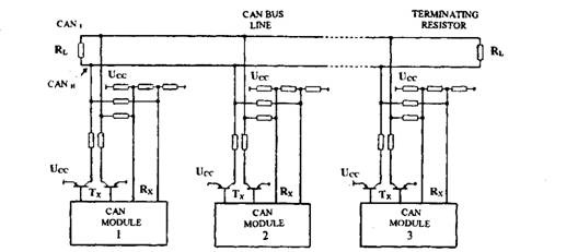
Fig. 13.49. Connection of CAN modules onto the CAN data bus.
Each ECU incorporates a pair of transmitter wires (labelled Tx) and a pair of receiver wires (labelled Rx). The transmitter wires are connected to the base terminals of a complementary pair of npn/pnp transistors which can switch the CAN_L line to a low voltage (close to 0 V) and the CAN_H line to a high voltage, denoted as Vcc (usually about 5 V). The receiver wires are connected to the bus line through a pair of resistors. CAN transfers data around the bus by using the principle of generating a voltage difference between the CANJL and CAN_H wires. When an ECU transmits a logic ’1′ data bit, it switches off its transistor pair. The resistor network connected to bus causes both the CANJL and CAN_H wires to assume approximately the same voltage level (about 2.5 V), and so there is no voltage difference between them. This is called the ‘recessive state’.
If a logic ’0′ is to be placed on the bus, the ECU’s transistor pair is switched on which produces a current through the terminating resistors. Consequently a differential voltage of 2 to 3 V is generated between the two wires of the bus. This is called the ‘dominant state’.
To receive data from the bus, the ‘dominant’ and ‘recessive’ states are governed by a resistor network, which changes the differential voltages on the bus line to the corresponding ‘recessive’ and ‘dominant’ voltage levels at the comparator input of the receiving circuitry. The receiver’s comparator then generates logic ’1′ and logic ’0′ data for use by the ECU.
13.2.4.
Basic Vehicle Circuits
A vehicle’s wiring system can be subdivided into a number of simple circuits which are connected in series. Each of these circuits consists of the battery, the electrical components, and its switch including the following three wires or cables.
(i) The feed wire which connects one of the battery
terminal posts of the switch ; (ii) The switch wire which connects the switch to the component;
(Hi) The return wire which connects the component to the second battery terminal post, either directly (Fig. 13.50) or indirectly through the frame of the vehicle (Fig. 13.51).
In a more elaborate wiring circuit, one switch controls
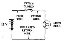
Fig. 13.50. Insulated-return circuit.
several sub-circuits having two or more components jointed together in series or parallel (Fig. 13.52). In addition, it may have overload fuses. Also one switch may have two ‘on’ positions, to switch circuits whenever necessary.
Earth Return.
All electrical circuits incorporate both a feed and a return conductor between the battery and the component requiring supply of electrical energy. The vehicle with a metal structure can be used as one of the two conducting paths. This is called as the earth return (Fig. 13.51). A live feed wire cable forms the other conductor. To complete the earth-return path, one end of a short thick cable is bolted to the chassis structure while the other end is attached to one of the battery terminal posts. The electrical
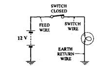
Fig. 13.51. Earth-return circuit,
component is also required to be earthed in a similar way. Only one battery-to-c hassis conductor is necessary for a complete vehicle’s wiring system and similarly any number of separate earth-return circuits can be wired. An earth-return system, therefore, reduces and simplifies the amount of wiring so that it is easy to trace electrical faults.

Fig. 13.52. Basic wiring circuit of vehicle.
Insulated Return.
Some vehicle application requires a separate insulated-cable system for both the feed and the return conductors. It is also safer because with separate feed and return cables, it is practically impossible for the cable conductors to short even if chafed and touching any of the metal bodywork, as the body is not live since it is not a part of the electrical circuits. From the safety reasons, an insulated return (Fig. 13.50) is essential for vehicles transporting highly flammable liquids and gases, where a spark could very easily set off an explosion or a fire. The vehicles, such as coaches and double-decker buses use large quantity of plastic panelling. For these vehicles an insulated return is more reliable and safer. The insulated return off course uses extra cable that makes the overall wiring harness heavier, less flexible, and bulky, consequently increases the cost to some extent.
Open Circuit.
When a wiring circuit is not continuous so that no current flows, then the system is called open-circuit. This situation may be normal such as when a switch breaks the circuit or it may be unintentional, due to poor connections, partially broken or connected terminals, or fractured or burnt-out wire. It is usually difficult to find out intermittent unwanted open circuits, which can cause damage to other electrical components. Permanent open circuits are normally easier to find.
Short Circuit.
Short circuit occurs in a wiring system when the insulation of a live cable is chafed so that the bare portion of wire either touches some part of the metal earth return, such as the chassis, or is crossed with another exposed piece of wire resulting in a closed circuit with the battery in series. This may cause sparking as the vehicle’s body vibrates. Also overheating at the short may take place, which can melt the insulation and expose more bare wire or other electrical connections. The battery also discharges rapidly due to continuous current flow. Eventually the wires may melt together and overload the shorted wiring so that it again overheats and burns through the wire, thereby becoming a potential source of fire hazard. Therefore the wiring circuits on the vehicle are safeguarded by fuses, which blow and prevent further current flow in the event of a short circuit.
