10.28
Types of Supercharger
There are two general types of supercharger pumps : (i) Positive displacement and (ii) Centrifugal.
The positive-displacement pumps are those in which every revolution pumps the same volume of air. They compress air by taking in a large volume and forcing it into a smaller area. These pumps include the reciprocating, the lobe (roots), and the vane designs.

Fig. 10.57. Roots blowers.
The Roots Blower.
This device was patented about 1865 in America and was used for a number of applications including (in very large sizes) ventilating mines. Figure 10.57 shows the general layout used for engine supercharging. Depending on engine size the width of the casing becomes about 150-300
mm. It is basically a gear pump where each gear (called a rotor) has only two teeth or lobes. Some Roots blowers contain rotors having three or even four lobes. A small clearance is provided inside the casing with the rotor, which are carried on shafts that are geared together outside the casing. One rotor shaft, driven at approximately at the engine speed, drives the other at the same speed.
The Roots blower is not a compressor but an air displacer. The air is simply carried round from inlet side to outlet side in the spaces between the lobes and the casing. The output pressure depends upon the relative swept volumes of the blower and the engine, and the blower speed. Since the rotors operate continuously against the full delivery pressure, more input power is necessary for this device than working as a compressor. However this power requirement is less at low pressures which increases rapidly with pressure rise. Due to the rotor clearance some ‘back leakage’ of air takes place, which increases as delivery pressure rises and decreases as speed increases. Therefore this type of supercharger is mostly fitted with high speed engines in those having relatively low supercharged pressures.
The Vane Compressor.
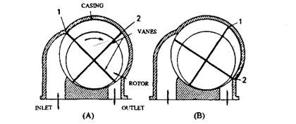
The vane compressor, in its simplest form, consists of a cylindrical casing. A cylindrical rotor carrying protruding vanes is mounted eccentrically in the casing so that the space between rotor and the casing has been divided into a number of compartments. The volume of these compartments varies as the rotor turns.
The position of maximum volume is shown in Fig. 10.58A where the vane (1) has just cut off communication between this compartment and the inlet port. In Fig. 10.58B, the rotor has turned to the position where the vane (2) is just about to open the compartment to the outlet port. The volume of the compartment in this position is smaller than earlier. By altering the position of the leading edge of the outlet port the amount of compression within the compressor can be changed, and normally this is arranged to match with the required delivery pressure.

Fig. 10.58. Principle of the vane compression.
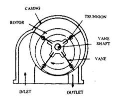
Figure 10.59 represents one form of this type of compressor which has been marketed under the names of Centric, Arnott and Shorrocks at various times. The vanes are mounted on a shaft, placed centrally in the casing. Each vane is supported on two ball bearings, in such a way that the vanes are always radial to the casing. The vanes pass through slotted rods or trunnions carried in the rotor. A very small clearance is provided between the tips of the vanes and the casing. The rotor is driven at the engine speed by belt, chain or gear drive.

Fig. 10.59. The trunnion-type radial vane compressor.
The vane compressor has one disadvantage that it requires lubrication due to the sliding action of the vanes in the rotor. Although the lubrication is easy to provide, but it is undesirable as oil mist carried into the engine may develop combustion difficulties, specifically in compression-ignition engines.
The Centrifugal Blower.
The centrifugal blower (Fig. 10.60) can be compared with a water pump used in an engine cooling system. But the impeller of the centrifugal blower is driven at considerably higher speed, and is designed and manufactured more carefully than the corresponding part of the water pump. The speed of the blower is five to six times of the
engine speed. Air drawn in through the intake is carried round between the vanes of the impeller and then thrown outwards by centrifugal force into the volute casing from which it passes to the inlet manifold.
The major advantage of this type of blower is that a considerable quantity of air can be delivered by a relatively small size. However, it has two main disadvantages for automobile use. One is the very high speed of rotation, which causes problem in the drive system during rapid accelerations and deceleration. The second is that it is efficient only over a very narrow speed range.

Fig. 10.60. Centrifugal blower.
