25.16.
Torque Converter
The torque converter, in addition to functions of the normal mechanical gear transmission, provides a smooth automatic vehicle pick up from standstill and torque multiplication. The performance characteristics of a hydrokinetic torque converter installed between the engine and the gear train is illustrated in Fig. 25.33 for light throttle and full throttle maximum output conditions over a vehicle speed range. The figure indicates that the initial torque multiplication when driving away from rest is considerable. Also the large gear ratio steps of the conventional transmission are reduced and smoothed out by the converter’s response between automatic gear shifts. In first gear (Fig. 25.33), maximum torque multiplication is provided by the torque converter at stall pull away conditions, which progressively reduces as the vehicle speed increases until the converter coupling point is reached. At this point, the reaction member free wheels. With further increase in speed, the converter changes to a simple fluid coupling so that

Fig. 25.33. Torque multiplication and transmitted power performance relative to vehicle speed for a typical four speed automatic transmission.
torque multiplication ceases. In second gear the converter starts to operate nearer the coupling point so that it contributes far less torque multiplication. In third and fourth gears the converter functions entirely as a fluid coupling operating beyond the coupling point as a result, there is no further torque multiplication.
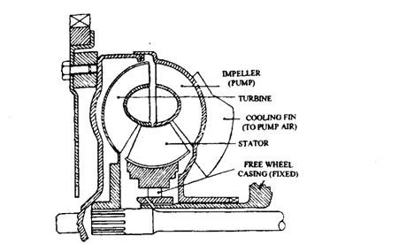
The torque converter multiplies torque through the force of fluid movement. All of its moving parts are submerged in lubricating oil. It transmits power silently and smoothly, without shock, at various speed and torque ratios. Its operation is fully automatic and reliable, normally requiring no service. The torque converter is enclosed in two-piece stamped steel shells or housings, which are welded together and shaped like a tyre. It has three functional parts ; the driving member or im^ller, the driven member or turbine, and the stator or reactor (Fig. 25.34). The impeller forms the back shell of the converter housing. The turbine drives the planetary gear train and is mounted on the transmission input shaft. The reactor is connected to the

Fig. 25.34. Torque converter parts.
transmission case through a one-way clutch mounted on a forward extension from the pump cover. The front housing is connected to the engine crankshaft through a drive plate. On the back of the converter, a rear hub is supported by a plain bearing located in the front of the transmission oil pump housing. The outer diameter of the converter is approximately three times of its inner diameter.
The hub of the converter housing drives the transmission oil pump, which produces oil pressure for the transmission controls and for keeping the converter full of oil in the pressurized condition (called charge pressure). Oil charge pressure is required to minimize formation of air pockets (called cavitation) near the converter centre due to centrifugal action of oil during rotation of the housing. The oil charge pressure ranges from 207 kPa to 1241 kPa for different transmission models.
The impeller blades, rotating at engine speed with the housing, impart kinetic energy to the oil and fling it towards outside of the housing. At the outer edge of the impeller the oil with high kinetic energy leaves the impeller and is thrown into the outer edge of the turbine, which provides a force to rotate the turbine. The turbine, which is connected to the drive wheels through the transmission gears and drive line, causes the movement of the vehicle. During the process as oil looses its kinetic energy, it moves towards the housing centre and consequently direction of flow of oil changes opposite to that of the impeller. Oil leaving the turbine in a backward direction hits the face of the stator blades. A free wheeling one-way clutch prevents stator backward rotation and stator blades redirect the oil with little energy loss to enter the impeller in the same direction of the rotation as that of the impeller. In this process the stator acts like a fulcrum in a lever system to increase torque transfer and it is said to be reacting.
Within the coupling, oil flows in two directions simultaneously, producing a very rapid spiraling oil flow that is like a coil spring with its ends brought together, called vortex flow. The vortex flow provides torque multiplication within the converter. As the turbine speed approaches the speed of the impeller, the amount of vortex flow is reduced, accompanied by a reduction in torque multiplication. At the coupling point the turbine speed reaches 85 to 90% of the impeller speed and at this point vary little vortex flow occurs, because all the converter parts rotate at nearly^he same speed.
Some transmissions use variable pitch blades in the stator, where blade angle can be changed over a range, from high to low angles. A high angle gives less oil flow restriction as the turbine speed approaches impeller speed and it minimises vehicle creep at idle. A low angle high torque conversion is provided because of a higher difference in speed between impeller and turbine. While variable angle blades result in substantially improved efficiency, they make the stator very expensive.
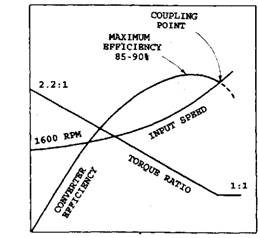
The greatest amount of vortex flow and torque multiplication is attained at stall condition, when the turbine is stopped and the impeller is rotating at its maximum speed. Maximum torque multiplication ratio at stall varies from 2:1 to 2.6:1. This ratio gradually and smoothly reduces as the turbine speed approaches impeller speed till the coupling point is reached. At coupling point, the oil leaves the turbine in a forward direction, hitting the back of the stator blade and the stator rotates forward on its one-way clutch, moving with the oil flow thereby producing minimum oil flow resistance. Stall speed of a converter, which is selected to prevent creep at idle, is about 70% of the engines maximum torque speed at full throttle. Operation at a high stall speed causes excessive heat generation, fuel consumption and noise. It also results in a high coupling point, which causes the engine to race. At high altitudes when engine output reduces, converter stall speed also lowers even with the same input torque. During coasting, the turbine accelerates the oil flow towards its outside and into the impeller where the oil’s energy is absorbed in trying to increase engine speed, due to which the stator is also forced to overrun. This type of operation, although not efficient, helps to slow the vehicle by transferring some of the vehicle’s energy to the engine. Figure 25.35 illustrated the converter performance.
A clutch is used to minimise drive line loss on some transmissions. It engages as the converter coupling point is reached by connecting the housing (which is bolted to the engine crankshaft) to the turbine so no slippage can occur between the converter input and output members, and smooth torque multiplication takes place during acceleration and lock-up at all road speeds.
The transmission oil cooler and the transmission gear train lubrication system provide restriction in the outlet of the oil flow to maintain converter charge pressure. Transmission oil is warned as it flows across warm mechanical parts while lubricating and cooling them. Forced oil circulation in the converter also heats the oil rapidly, especially at low speeds. Under severe operating conditions, oil temperatures may reach as high as 423 K, but the normal maximum limit is 408 K.
The recommended minimum operating temperature for automatic transmission oil is 361 K and temperatures lower than this produce sluggish action.
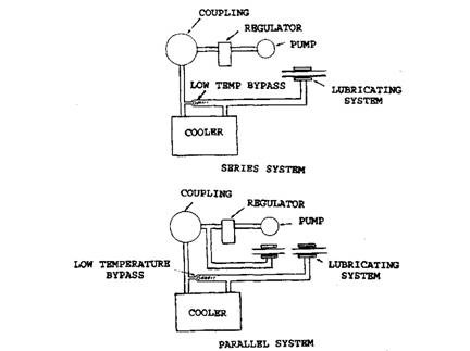
Transmission oil cooler is located in the radiator outlet tank where the engine coolant temperature is lowest. This arrangement provides maximum transmission oil cooling. Flow of oil in the cooling system takes place in series and parallel arrangements. A series system sends the total quantity of oil through the cooler and then to the transmission system where as a parallel system sends part of the oil to the cooler and part to the lubrication system. Figure 25.36 illustrates both the types of oil circulation.
The arrangement of three-element single-stage converter, shown in Fig. 25.37, is quite common and is used in conjunction with many different types of automatic gearboxes. The fluid for the converter is normally supplied by the automatic gearbox and it is generally a low viscosity mineral oil which contains additives to improve lubrication and resist frothing. Cavitation noise
caused by air in the converter is minimized by pressurizing the fluid to about 138 kN/m2. It can be seen in the figure that the free wheel is the only mechanical component, which can produce faulty operation of the converter. A fault in the free-wheel can produce the following.
Slipping stator.
This causes the fluid to enter the pump at the incorrect angle so that full torque multiplication cannot be obtained.
Seized stator. If fluid strikes the back of the stator vanes then the stator cannot work as free-wheel at the appropriate time because the fluid acts as a severe brake on the engine and produces overheating of the converter.

Fig. 25.35. Torque converter performance
OUTPUT RPM/INPUT RPM

Fig. 25.36 Series and parallel transmission oil cooling system.
A stall test indicates whether slip is occurring at the converter free wheel or in the gearbox. A general outline of the test method is as follows :
(i) Check that the engine is warm and is in good condition. A low engine power indicates
a false result.
Hi) Connect a tachometer to the engine.
(Hi) Check the wheels and apply the handbrake and footbrake.
(iv) Run the engine, select “L” (or position recommended by the manufacturer), fully depress the throttle and note the maximum engine speed, which should be about 1800 rpm.

Fig. 25.37. Three-element single-stage converter.
| Engine speed | Probable cause |
| Below 1000 rpm | Converter free-wheel slip |
| About 1200 rpm | Engine not giving full power |
| Above 2000 rpm | Gearbox clutch or band slip. |
During this test the engine power is absorbed by the converter fluid. This causes a rapid temperature rise due to which the duration of the test should be less than 10 seconds.
25.16.1.
Torque Converter Lock-up
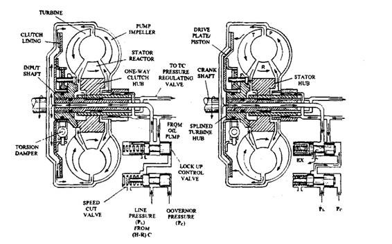
A lock-up friction clutch (Fig. 25.38) is incorporated between the input pump impeller and the turbine output shaft to overcome the inherent problem of relative slip, which always occurs between the torque converter’s pump impeller and the turbine runner, even while driving at moderate speeds under light load conditions. To realize maximum benefit of this lock-up the torque converter is allowed to operate when light torque demands are made on the engine and only when the converter is operating above its torque multiplication range that is beyond the coupling point. Consequently, converter lock-up is only permitted to be implemented when the transmission is in either third or fourth gear. As a result the power transfer is bypassed through the circulating fluid, instead transmitting the engine’s output directly to the transmission input shaft. This eliminates drive slippage, thereby increases the power actually propelling the vehicle. Consequently there is a net gain in power output, and the fuel wastage is reduced.
The lock-up clutch uses a sliding drive plate, which performs as the fiction coupling device and acts as a hydraulic controlled piston to energize or de-energize the clutch engagement facings. The lock-up drive plate/piston is supported by the turbine hub, which itself is mounted on the transmission input shaft. A transmission damper device, similar to that used on a conventional clutch drive-plate, is installed in the lock-up plate to absorb and dampen shock impacts during the engagement of the lock up clutch.
A speed cut valve and a lock-up control valve control the automatic operation of the converter lock-up. The function of these valves is to open and close fluid passages, which supply and discharge fluid from the space formed between the torque converter casing and the lock-up drive plate/piston. The speed cut valve prevents fluid escaping from the space formed between the converter casing and lock-up plate/piston through the lock-up control valve when there is a high governor pressure, but the transmission has not yet changed to third or fourth gear. Under these conditions, there is no line pressure in the high and reverse clutch circuit, which is controlled by the shift valve. Therefore, when the speed cut valve plunger moves to the left there is no line pressure to actuate the lock-up control valve so that the lock-up plate/piston remains pressurized on both sides in the disengaged position.
With the vehicle driven in either first or second gear at relatively low speeds, low governor pressure allows the speed cut and lock-up control valve return springs to push their respective plunger to the right. Under these conditions, pressurised fluid from the torque converter flows into the space separating the lock-up plate/piston from the turbine. Simultaneously, fluid from the oil pump is conveyed to the space formed between the torque converter’s casing and the lock-up plate/piston through the lock-up control valve and the central axial passage in the turbine input shaft. Consequently, the pressure on both sides of the lock-up plate is equalized and so the lock-up plate/piston cannot exert an engagement load to energise the friction contact faces (Fig. 25.38A). This is disengaged position of the lock-up.

Fig. 25.38. Lock-up clutch. A. Lock-up disengaged. B. Lock-up engaged.
For lock-up engagement, the speed of the vehicle rises, and increased governor pressure forces the speed cut valve plunger against its spring until it uncovers the line pressure passage leading into the right hand end of the lock-up control valve. Line pressure fed from the high and reverse clutch is directed through the speed cut valve to the right hand end of lock-up control valve, so that its plunger is pushed to the left to uncover the lock-up clutch drain port. Simultaneously, pressurized fluid from the chamber created between the torque converter casing and lock-up plate/piston escapes through the central input shaft passages and the wasted region of the lock-up control valve plunger back to the inlet side of the oil pump. The difference of pressure across the two sides of the lock-up plate/piston causes it to slide towards the torque converter casing until the friction faces contact. As a result the exit for the converter fluid is closed so that full converter fluid pressure is exerted against the lock-up plate/piston. This causes the input and output shafts to be locked together so that they rotate as one (Fig. 25.38B).
