9.27.
Throttle Body Injection
9.27.1.
Bosch Mono-Jetronic System
The Mono-Jetronic and Motronic injection systems have many features similar to those of the Bosch L-variants, but are quite different from them. Bosch offer Motronic M3 and Mono-Motronic versions. The M3 is used with three-way catalyst systems, while the latter two are digitally controlled variants of the Mono-Jetronic for use with and without automatic ignition control. Among those of other manufacturers are the Weber LAW, and GM Multec single- and multi-point injection systems.
Bosch Mono-Jetronic system (Fig. 9.117) is a cheaper variant. A single injector injects fuel intermittently into the throttle body. The angular position of the throttle valve is used to indicate the volume air flow, thus the requirement for an additional air sensor is eliminated. A low pressure vane type pump, installed in the fuel tank, delivers fuel at a pressure of 98 kPa, through a filter directly to the throttle body injection unit. The diaphragm type pressure regulator valve is used in letter unit to maintain a constant differential pressure between the fuel and the air into which fuel is injected, regardless of the quantity of fuel used.

Fig. 9.117. Mono-Jetronic injection system.
The ignition system provides the controller the signal of the engine speed. Among the other sensors, the throttle valve potentiometer together with engine speed and air temperature signals indicates the mass of the air flow. The air temperature sensor is installed in the air passage through the throttle body. The throttle valve potentiometer also signals the enrichment for the idle, acceleration and full load conditions, and in association with the engine speed indication, cuts off the fuel supply during overrun condition or, if required, limits the engine speed. A sensor incorporated in the cylinder block coolant jacket signals engine temperature to
the controller used for control of cold starting, immediate post-start operation and progressive warm-up. Battery voltage affects the response time of the injector valve, so compensation for this is provided in the controller, which signals to the solenoid valve for opening and closing the injector valve.
The thermo-actuator regulates the position of the throttle stop in the open loop idle speed control. The throttle valve potentiometer signals to the controller for providing extra fuel to maintain the correct air-fuel ratio. When a closed loop idle speed control system is used, the thermo-actuator is replaced by a servo-motor which, by varying the throttle opening appropriate to engine speed and temperature signals, controls the air supply to the engine to
adjust any deviation from the value required for idling speed. Both these systems are maintenance-free, because no adjustment is required manually for the engine speed or mixture for idling and, in case of the closed loop system, compensation is affected automatically for drift due to wear of the engine or injection system.
Operation and Control.
The digital control unit processes the input signals and then computes the duration of injection at constant pressure to indicate the quantity of fuel to be injected per engine cycle. The control unit is consisted of an analogue-digital converter, a microcomputer, and programme and data memories. To compute the basic injection period, it refers to an engine characteristic map comprising 15 throttle angle and 15 engine speed points, making a total of 225 data points for maintaining the air-fuel ratio at lambda 1.0, for part load operation. An adaptive map comprising 8×8 data points is superimposed on this 15 x 15 map. If the air-fuel ratio varies from prescribed limits, an adaptation algorithm writes correction values into the former. This also compensates for deviation in the performance of either the engine or injection equipment, due to wear in service.
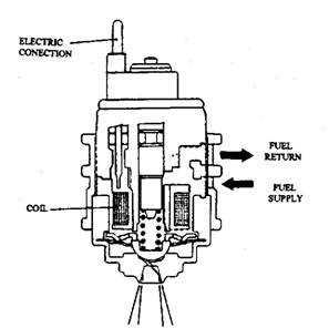
The injection pulses are timed relative to signals from the ignition system. Enrichment for cold starting, post start and warm-up, full load and acceleration are carried out in response to the signals as discussed above. Because all cylinders are supplied through one injector, the volume injected per cycle is large, so a single-hole unit can be inadequate. Therefore, six angled radial holes in the tip of the injector (Fig. 9.118) produce a conical spray. This is divided into two segments directed one into each of the crescent shape apertures opened up between the edges of the butterfly valve and the bore of its housing. The spray characteristics are optimised by a combination of baffle and swirl effects.

Fig. 9.118. Low pressure fuel injection valve assembly.
