25.9.
Synchromesh Gear-box
For wider ranges of engine speed (1000 to 6000 rpm), higher car speeds (160 km/h and more), and high speed motorways, it is desirable, and even in some cases essential, to increase the number of traditional four speed gear ratios to five where the fifth gear, and sometimes also the fourth gear, have the overdrive ratio. Increasing in the number of ratio steps provide several advantages. The extra gear provides better acceleration response, enables the maximum engine rotational speed to be reduced while cruising in top gear, improves fuel consumption, and reduces engine noise and wear. Typical gear ratios for four speed gearboxes are provided in section 25.1. The following section deals with five speed synchromesh gearboxes used in longitudinal and transverse mounted engines.
25.9.1.
Five-speed and Reverse Double stage
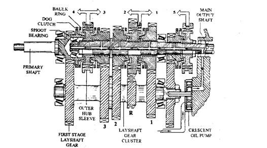
In the five speed double stage gearbox layout, the power input to the primary shaft passes to the lay-shaft and gear cluster through the first stage pair of meshing gears, so that motion is relays to all the second stage lay-shaft and main-shaft gears (Fig. 25.19). Each pair of second stage gears has a different size combination, due to which complete range of gear ratios is obtained. In neutral position each main-shaft gear revolves on the main-shaft at certain relative speed to it. The output power flow is provided by locating the selected main-shaft gear with the main shaft, so that the flow path from the input shaft is completed to the first stage gears, second

Fig. 25.17. Single-rail gear-selector arrangement.

Fig. 25.18. Gear-selection mechanism with single-rod and caliper interlocking device.
stage gears and finally to the main shaft. The fifth gear being an overdrive gear in this case, to speed up the main shaft output relative to the input shaft, a large lay-shaft fifth gear wheel is meshed with a much smaller main shaft gear.
A forced feed lubrication system is incorporated for heavy duty operations, which uses an internal gear crescent type oil pump driven from the rear end of the lay-shaft (Fig. 25.19). The oil is drawn from the base of the gearbox casing by this pump, and then pressurized and forced through a passage to the main shaft. Subsequently the oil is transferred to the axial hole along the centre of the mainshaft through an annular passage formed between two nylon oil seals. The mainshaft gears are lubricated through radial branch holes.
25.9.2. Five speed and Reverse Single-stage
This two shaft gearbox uses one gear reduction stage, incorporating pairs of different sized constant mesh gear wheels to provide a range of gear ratios. Compared to the two pairs necessary in the double stage gearbox for gear ratio, in this layout only one pair of gears mesh and hence frictional losses are halved. Power from the input primary shaft can follow five different flow

Fig. 25.19. Five speed and reverse double stage synchromesh gearbox.
paths to the main secondary shaft through first, second, third, fourth and fifth gear wheel pairs, however only one pair can transfer power drive at any one time (Fig. 25.20). In the neutral position, first and second output gearwheels are driven by the corresponding gearwheels attached to the input primary shaft, but they are free to revolve about the output secondary shaft. Third, fourth and fifth gear wheel pairs are driven by the output second shaft and are free to revolve about the input primary shaft.
For any individual gear ratios, the particular synchronizing sliding sleeve is pushed towards and over the dog teeth forming part of the selected gearwheel. Hence, for first and second gear ratios, the power flow takes place from the input primary shaft and constant mesh pairs of gears to the output secondary shaft through the first and second drive hub attached to this shaft. The synchronizing sleeve then locks the selected output gearwheel to the output secondary shaft. Third, fourth and fifth gear ratios are obtained when the third and fourth or fifth gear drive hub, fixed to the input primary shaft, it locked to the respective gear wheel dog clutch. The power flow path is from the input primary shaft drive hub and selected pair of constant mesh gears of the output secondary shaft.
Transfer of power from the gearbox output secondary shaft to the different left and right hand drive shafts is affected through the final drive pinion and gear wheel having a permanent gear reduction (Fig. 25.21). Power now passes from the differential cage that holds the final drive gear wheel to the cross-pin and planet gears where it divides to flow to the two side sun gears, so that power is transferred to both stub axle drive shafts.
