31.12.
Stability of a Vehicle Taking a Turn
31.12.1.
A Four-wheeled Vehicle
Let a vehicle take a turn to the left as shown in Fig. 31.11,
where,
C = radius of curved path measured at C.G. of the
vehicle, m r = wheel radius, m a = wheel track, m b = wheel base, m
h = height of C.G. of the vehicle from ground, m I = distance of C.G. in front of r«sar axle axis, m V = linear speed of the vehicle on the road, m/s W = weight of the vehicle, N.
(t) Reaction at the Wheels due to Weight. Let
RlF and Rm be the normal reactions at the inner front and inner rear wheels respectively and Rof and Ror be the normal reactions at the outer front and outer rear wheels respectively, then as discussed sections 31.8.2.


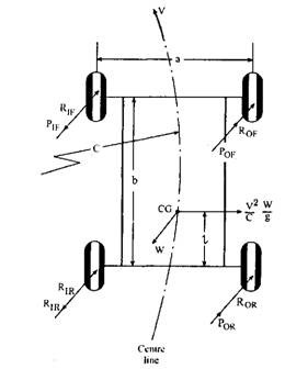
Fig. 31.11. Forces acting on a four-wheeled vehicle while taking a turn.
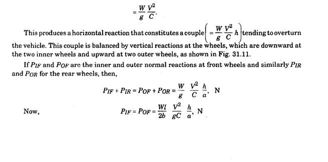
(ii) Reaction at the Wheels due to Centrifugal Force. The centrifugal force acts outwards through C.G. of the vehicle with magnitude,

(mi) Reaction at the Wheels due to Gyroscopic Effect. If a body revolves about OX and a couple, called gyroscopic couple, is applied along OY, then the body tries to process about axis OZ. This is called gyroscopic effect. The planes of spin, gyroscopic couple and precession are mutually perpendicular. The direction of precession is such that the axis of spin tends to place itself in line with the axis of the applied torque (i.e. gyroscopic torque) and in the same sense.
The magnitude of applied gyroscopic couple = / w cop where / = the polar moment of inertia of the body
(0 = angular velocity of spin and = angular velocity of precession.
The reaction couple exerted on the body is equal in magnitude to the applied couple but opposite in direction.
When the vehicle takes a turn the gyroscopic effect appears due to :
(a) the precession of rotating wheels and other parts either rotating at the engine speed or the wheel speed but parallel to the plane of rotation of the wheel.
(b) the precession of engine parts and also other rotating either at engine or wheel speed but perpendicular to the plane of rotation of wheel. The axes of rotation in (a) and (b) are horizontal.
The gyroscopic effect may also appear when the vehicle nose rises or falls suddenly due to surface irregularity and the engine is processed. The wheels are also processed when one wheel is lifted or lowered due to passage over a bump or a pot hole. These cases have been dealt with in example 31.9.
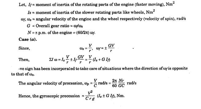
The magnitude of vertical reaction due to this couple is same at the outer and inner wheels and its effect (reaction couple) is to roll the car in an outward manner similar to that caused by the centrifugal effect. The situation is shown in Fig. 31.12.
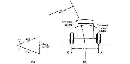
Fig. 31.12. Effect of gyroscopic reaction couple.
If Qif and Qof are respectively inner and outer vertical reactions at the front wheels and Qm and Qor are similarly at the rear wheels, then,

In this analysis, Is represents the moment of inertia of all the wheels taken together, and the moment of inertia of the individual wheels have been assumed to equal one another. If the moment of inertia of front and rear wheels are different then while calculating individual reactions at the wheels, the respective moment of inertia should be used; but for calculation of the total gyroscopic torque, individual moment of inertia can be added, giving 7S = Uu>, where 7(0 = moment of inertia of the wheels. This is because the velocity of spin and the velocity of precession are the same for all the wheels.
Case (6).
![]()
but here, Is stands for the moment of inertia of the slower moving parts rotating in a plane parallel to the plane of the rotation of the engine. The -ve sign takes care of the rotation in a direction opposite to that of the engine.
![]()

Let the engine rotate in the clockwise direction when viewed from the front. Then the reaction couple tends to lift the rear wheels and depress the front ones as shown in Fig. 31.13. Thus the effect is to increase the front wheel loads or decrease the rear wheel loads by

Fig. 31.13. Effect of reaction couple due to rotation of engine.
If during a left-hand turn, the engine rotates in the anti-clockwise direction when viewed from the front, the effect of the reaction couple due to the engine gyroscopic couple is just the reverse of the above situation, i.e., the reaction couple tends to lift the front wheels and depress the rear ones.
Now if the vehicle takes a right-hand turn, the above results for the inner and outer wheels are not affected both in magnitude and direction but the gyroscopic torque due to engine is only affected in direction and is opposite to that in the above cases.
When the vehicle takes a turn, the present analysis reveals that precessional (that of wheels) and centrifugal effects are added together and act in a direction opposite to the static distribution of the load at the wheels tending to overturn it. Considering the sum total of the reactions at the inner and outer wheels it can be stated that the parameters responsible for overturning are as follows :
(i) When the vehicle is taking a turn at high speed, i.e. co is high.
(ii) When the loaded vehicle is sufficiently high over the ground i.e., h is high. (Hi) When the vehicle is taking a sharp turn, i.e. C is small.
(iv) When the vehicle is overloaded, i.e. W is high.
In this article, the case of the vehicle taking a turn on a level is considered. If the turning of the vehicle on a banked track is considered, then an additional parameter, 8, the inclination of the wheel axes to the horizontal, appears. Section 31.11 gives partial treatment of this situation where gyroscopic effects have not been considered. Example 31.8 may be referred to further understanding.
31.12.2.
Two-wheeled Vehicle
When a two-wheeler takes a turn, to counteract the over-turning effect it has to heel-over towards the centre of turning as shown in Fig. 31.14. As may be clear from the figure the turning of the vehicle to the right is considered.
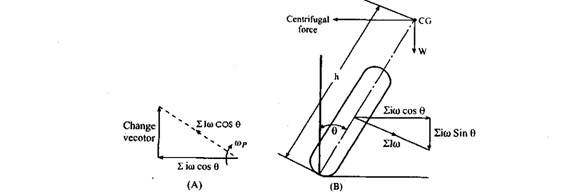
Fig. 31.14. Forces acting on a two-wheeled vehicle while taking a turn.
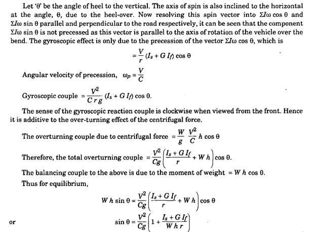
Example 31.9. A motor vehicle having a rigid rear axle is travelling along a straight level road at 160 km I hr. The rear wheel on the left-hand side of the vehicle drops into a pot hole, which
lowers the end of the axle by 75 mm. The track of the vehicle is 1.5 m, the rolling radius of the wheels is 0.3 m and the movement in and out of the pot hole may be regarded as approximating in from of a complete sine wave, 0.45 m long, having its mean 0.005 hi below the road level. The
I 2
polar moment of inertia of the axle with its two wheels is 27 Nm . Determine the maximum gyroscopic couple that acts on the vehicle and the effects of this op. the course of the vehicle. Solution.
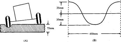
Fig. 31.15. Diagrammatic representation of fall of the wheel into a pot-hole.
Figure 31.15A shows diagrammatically the fall of left side rear wheel into pot hole while Fig. 31.15B shows the shape of the pot hole forming a sine wave. In this type of problem, the evaluation of the precessional velocity is a bit involved. It can be assumed that the wheel drops into the hole and rises out of it with simple harmonic motion giving, (Dp, max = Constant x Angular amplitude.
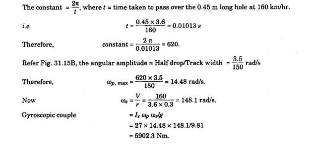
Figure 31.16 shows the momentum vector in end view and the gyroscopic torque producing the change of momentum vector. The vehicle yaws in the direction shown due to reaction of gyroscopic couple.

Fig. 31.16. Gyroscopic couple.
